Variable Voltage Converter
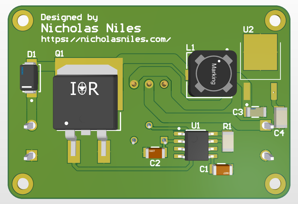
Circuit Board
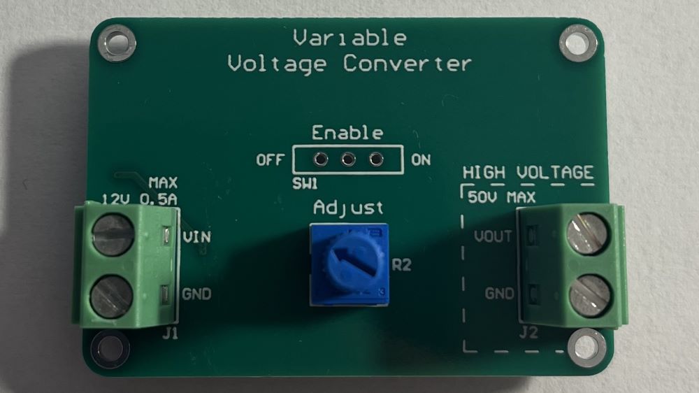
The Variable Voltage Converter is a device that takes in an input voltage up to 12V and outputs a converted voltage at the output terminals, either higher or lower than the input voltage. This output voltage can be adjusted via a potentiometer on the board. It also has a main power switch that toggles the input voltage to the converter circuit.
This project is sponsored by PCBWay, a wonderful and easy to use PCB manufacturer.