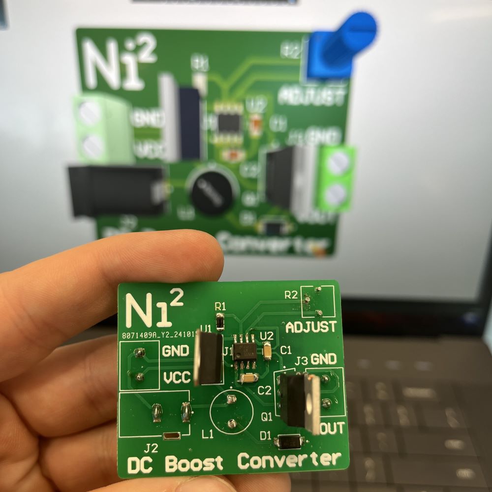
Variable Boost Converter
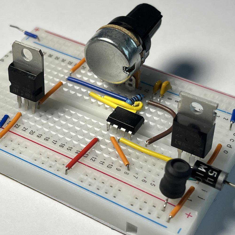
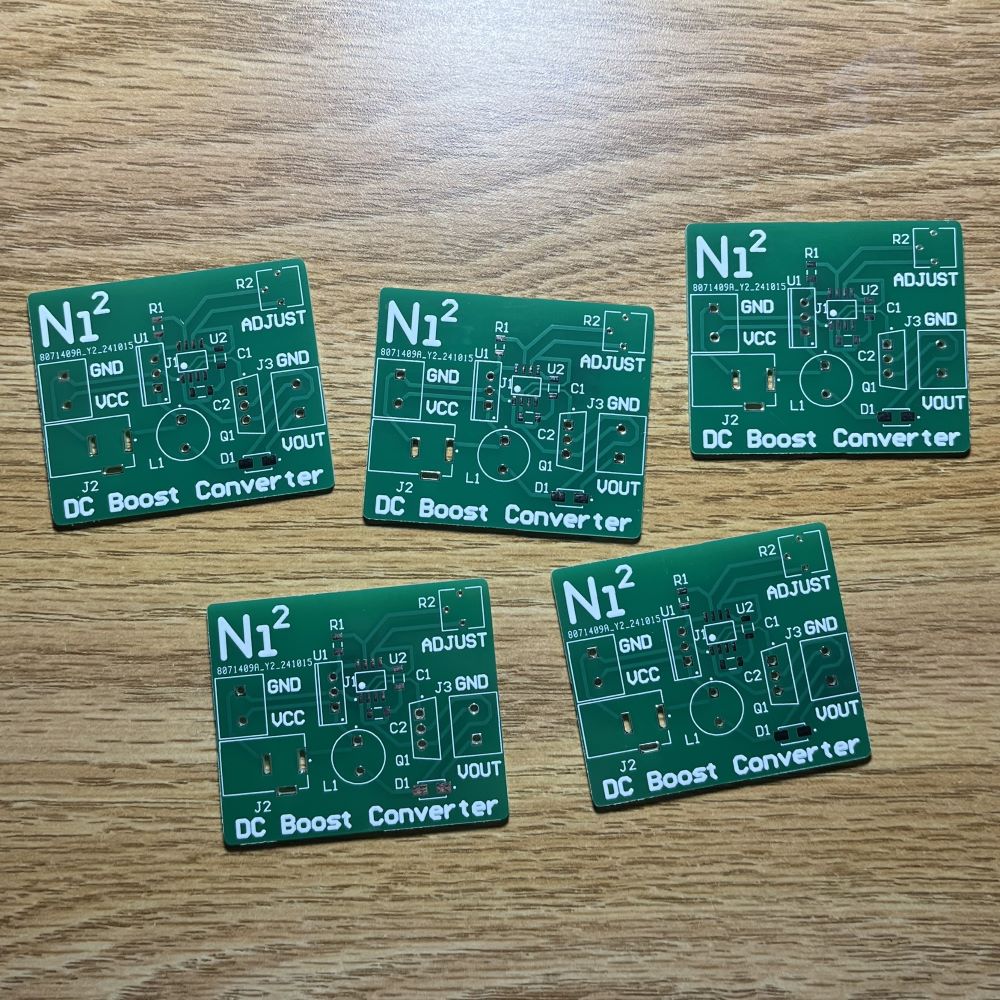
Circuit Board
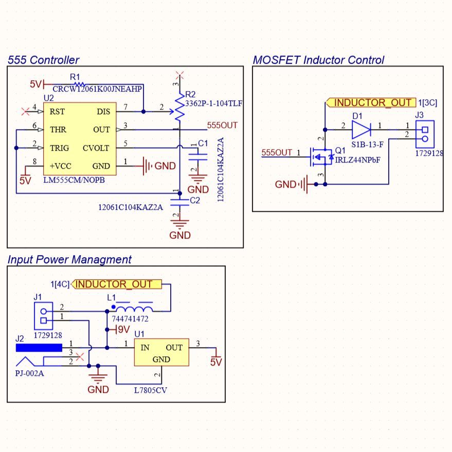
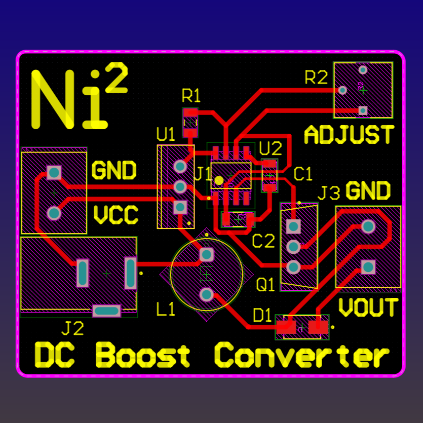
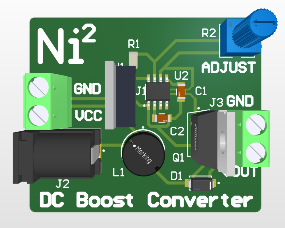
This DC-DC Boost Converter device able to multiply an input voltage up to 10x at the output. It utilizes primarily an LM555 IC in tandem with an inductor and MOSFET. Its output voltage is adjustable via the potentiometer.
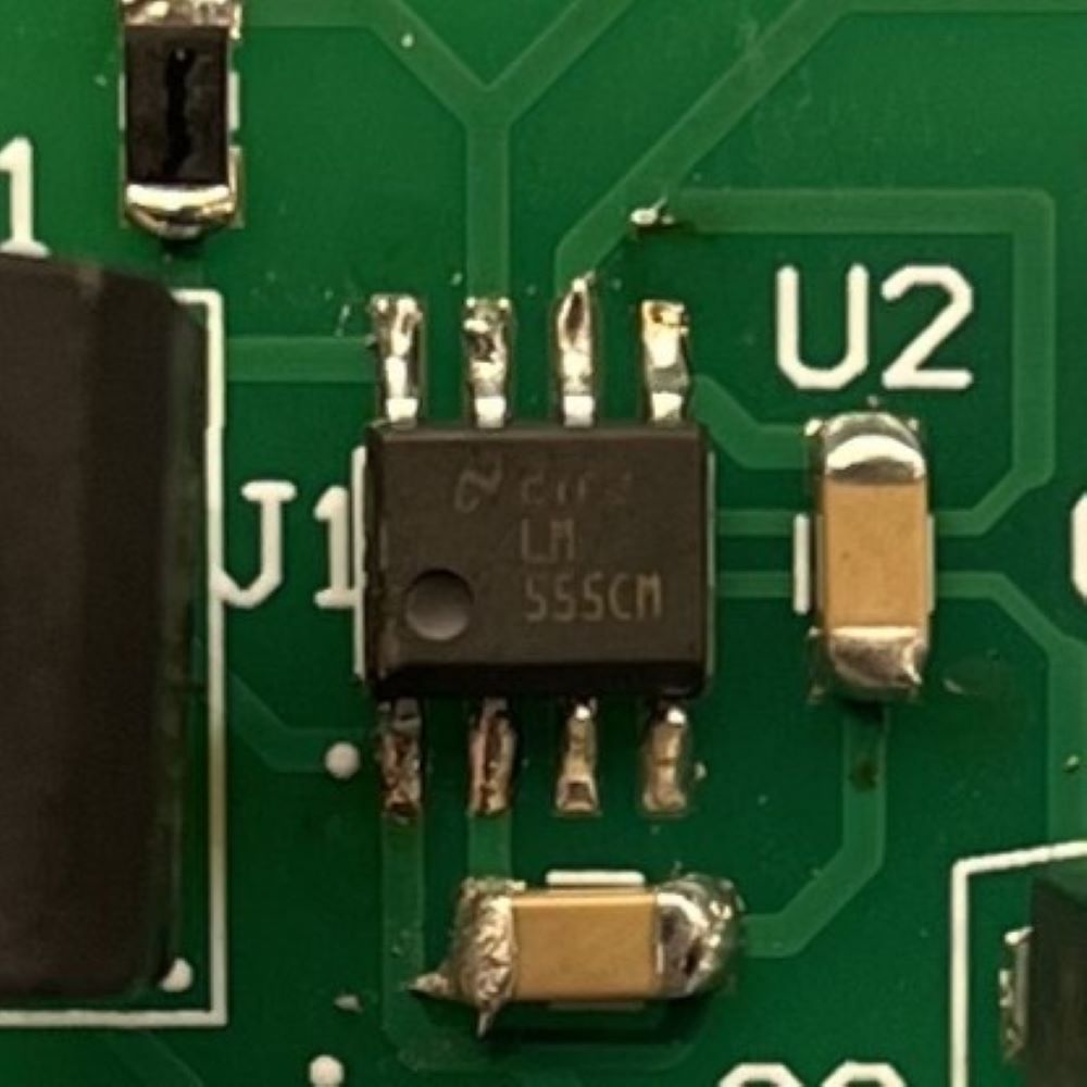
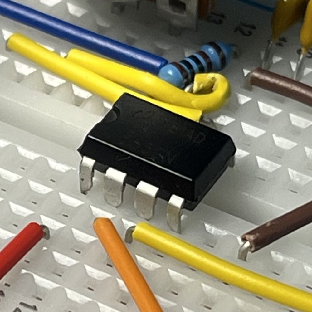
The 555 IC at the heart of the circuit outputting an adjustable signal.
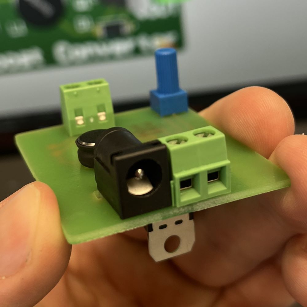
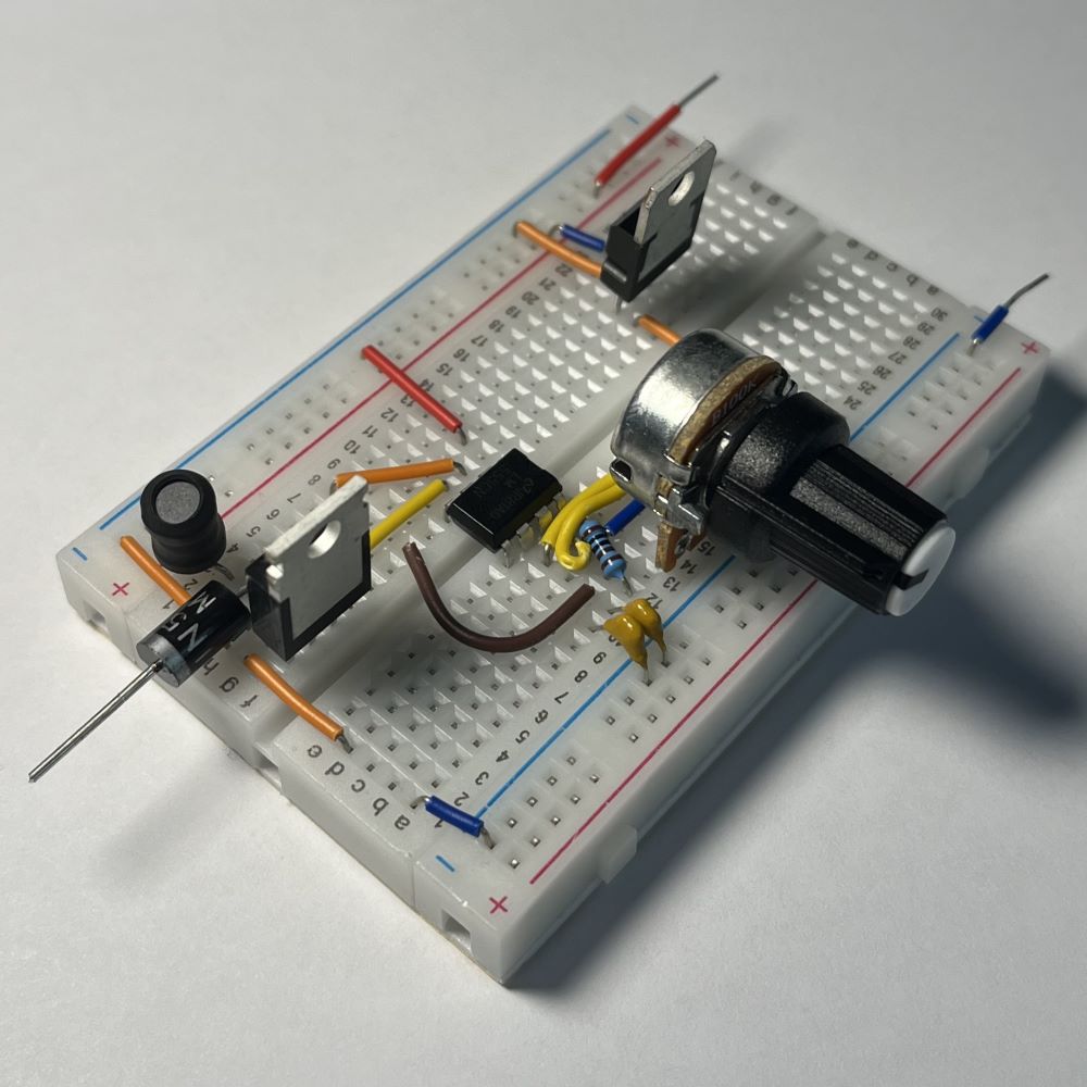
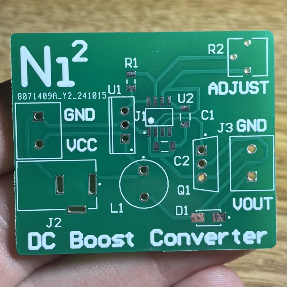
The underside of the PCB showing the inductor and potentiometer.