Device Pinouts
Below is information and necessary tables of pinouts for the device.
| Pin Technical Name |
Pin Name |
Pin Info |
| J1 |
USB-C Port |
General Power, Programming, or UART Port |
| I01 |
1 |
I/O Pin |
| IO2 |
SDA |
I/O Pin or SDA Pin |
| IO3 |
SCL |
I/O Pin or SCL Pin |
| IO4 |
4 |
I/O Pin |
| IO5 |
5 |
I/O Pin |
| IO6 |
6 |
I/O Pin |
| IO7 |
7 |
I/O Pin |
| IO9 |
9 |
I/O Pin |
| IO10 |
10 |
I/O Pin |
| 3V3 |
3.3V |
Voltage Pin |
| 5V0 |
5V |
Voltage Pin |
| GND |
GND |
Ground Pin |
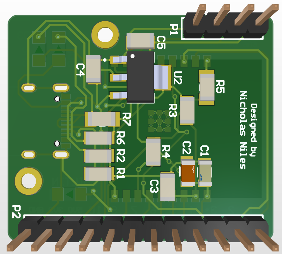
>
| P1 - 1 |
3V3 |
UART Voltage Pin |
| P1 - 2 |
TXD |
Microcontroller TX Pin |
| P1 - 3 |
RXD |
Microcontroller RX Pin |
| P1 - 4 |
GND |
Ground Pin |
Setting Up & Using the Device
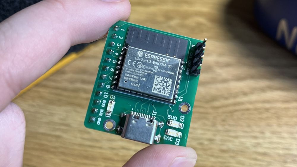
When it comes to using the device or soldering one for yourself, there are a few things to note. After finishing soldering, when first plugging the device in, you should hear (if on Windows)
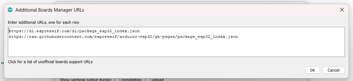
a consistent USB disconnect sound effect. This tells you you did it correctly. In the "Arduino IDE, go to File > Preferences > Additional Board URLs". Once done, add the following two links
into the additional board URLs list, and save:
	https://dl.espressif.com/dl/package_esp32_index.json
	https://raw.githubusercontent.com/espressif/arduino-esp32/gh-pages/package_esp32_index.json
Once done, set the target board to the ESP32 C3 Dev Board option. Also note, when programming the device, to set "USB CDC On Boot" to ENABLED. You can follow the settings shown below:
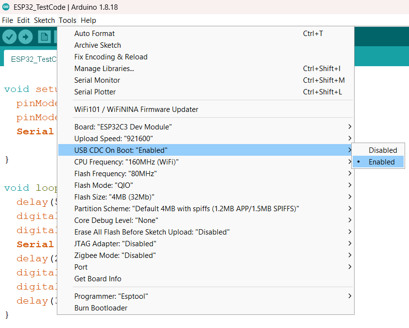
Now, once selecting the COM port that the device is connected to via USB-C, you can program as you'd like! Some sample code to test the board, which will blink the onboard LED
(as well as pin 6 if you hook that up to a breadboard and LED) periodically to show that it is programmed correctly. The console should also confirm that the device has been programmed.
Additionally, the device should be setup for serial if all the steps were followed correctly, so initializing serial and printing as needed should work like any other board, and
information should appear in the serial monitor if done right. One thing to note is, if a program you upload makes the device appear bricked (stuck boot looping, can't upload a program, etc.)
you must unplug the device, wire pin 9 on the board to ground, and plug it back in shorted and reprogram it with a new program. This will bypass any program currently on it that may be
breaking it. Handy to know!