Temperature Box Mk. 2
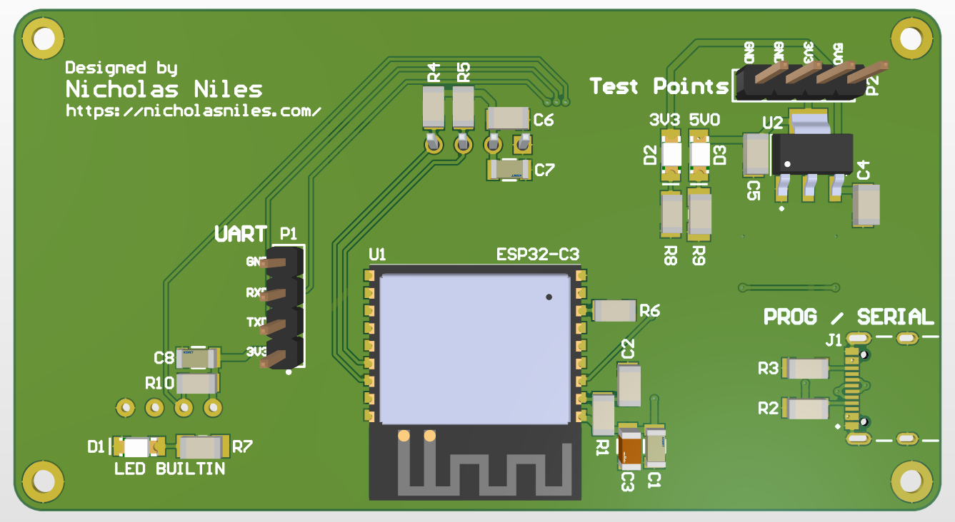
Circuit Board
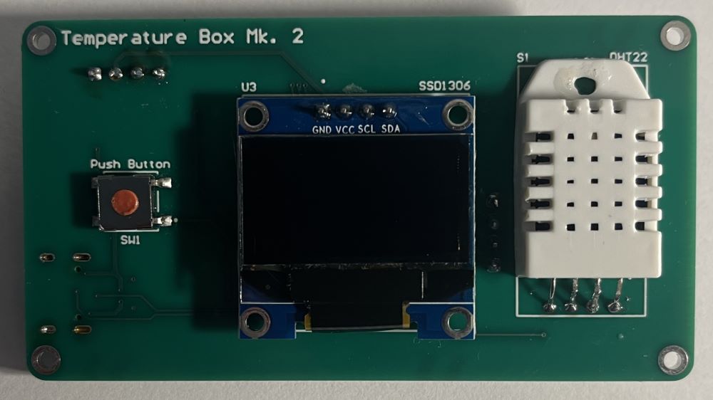
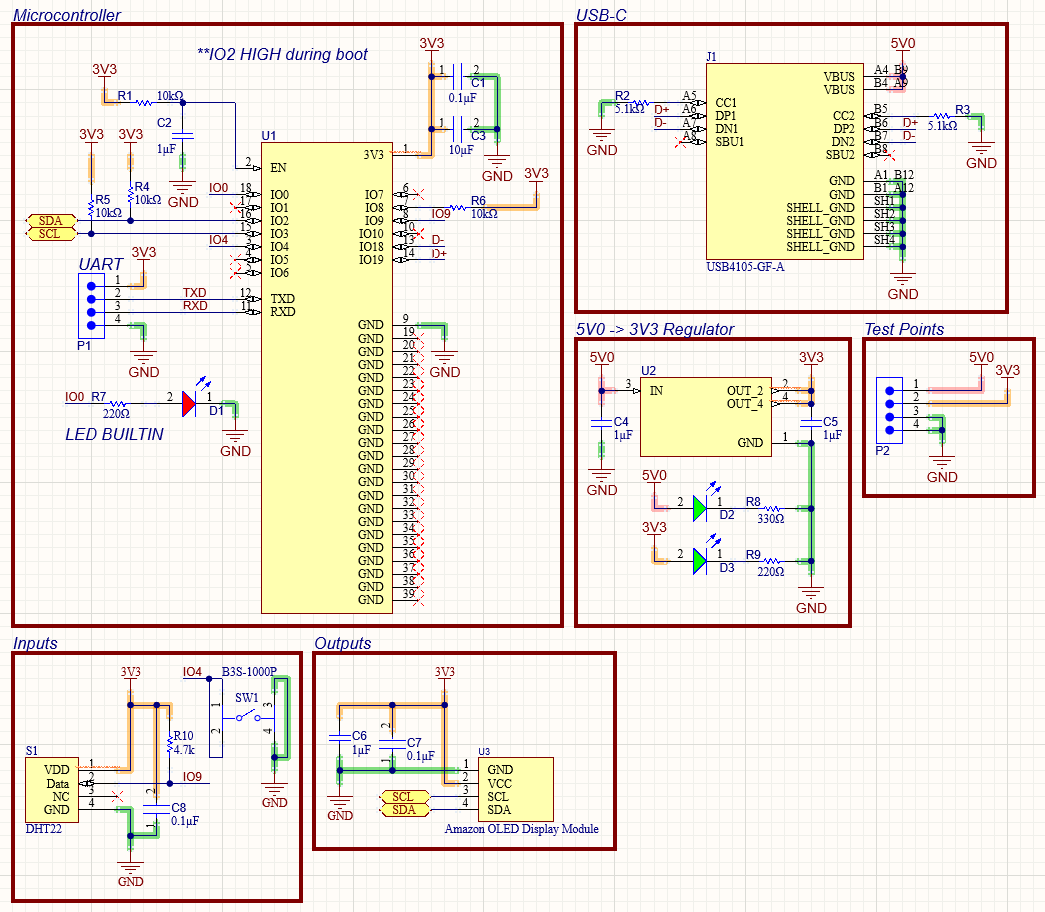
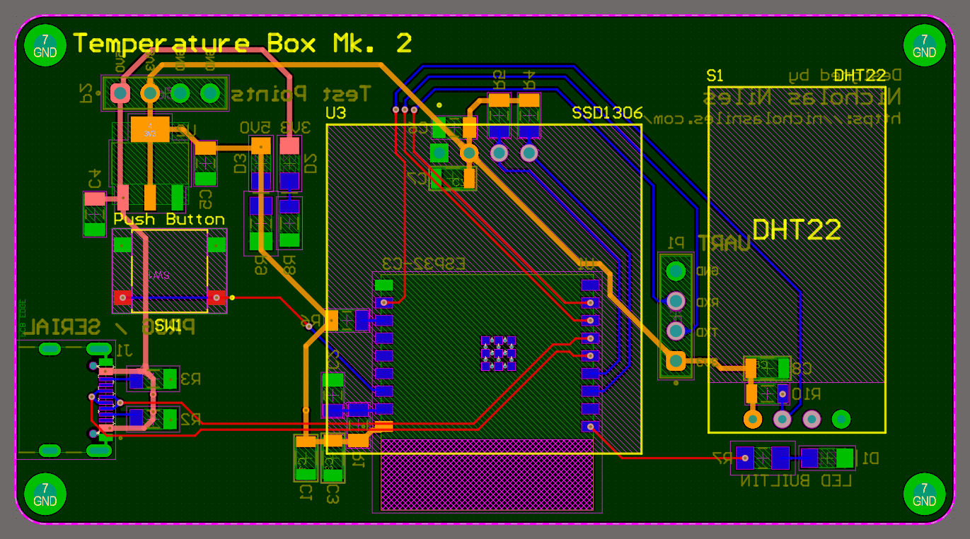
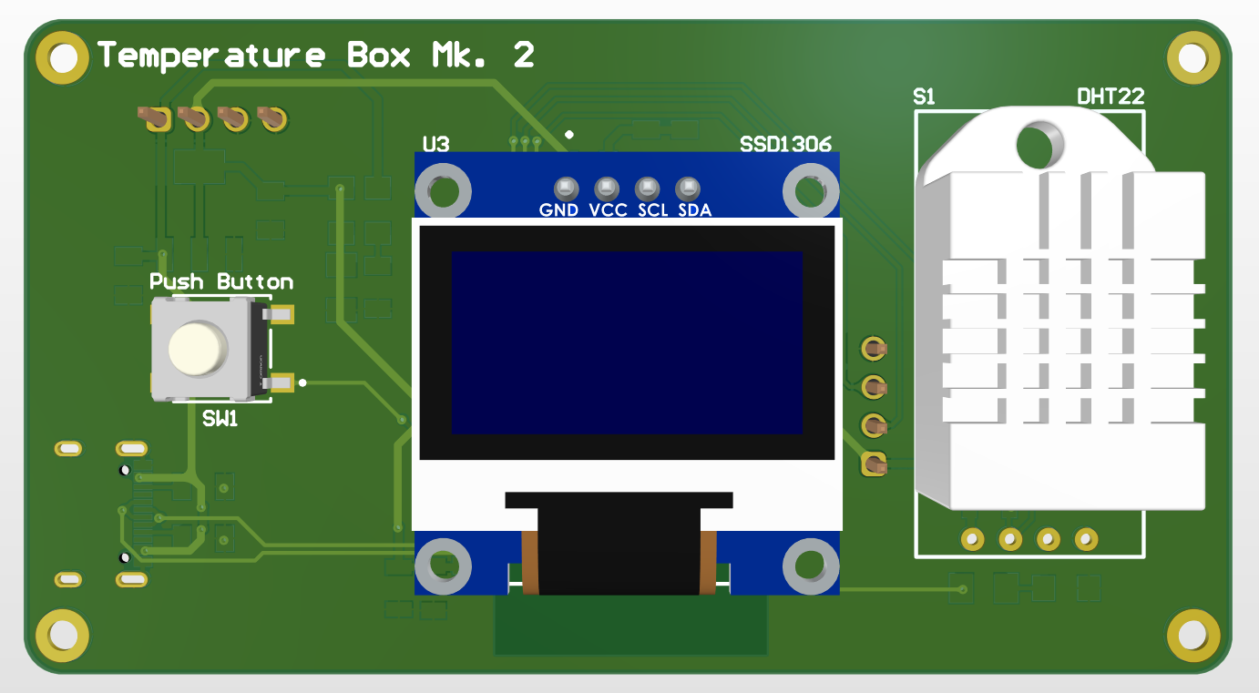
The Temperature Box Mk. 2 is a PCB that runs on an ESP32-C3 microcontroller, sampling the air temperature and humidity from a DHT22 sensor. The temperature or humidity is then displayed on a small OLED display, and the user can toggle between displaying temperature or humidity on that screen using a push button on the left side of the board. This project is a Mk. 2 and much-improved version of my original Temperature Box.
This project is sponsored by PCBWay, a wonderful and easy to use PCB manufacturer.