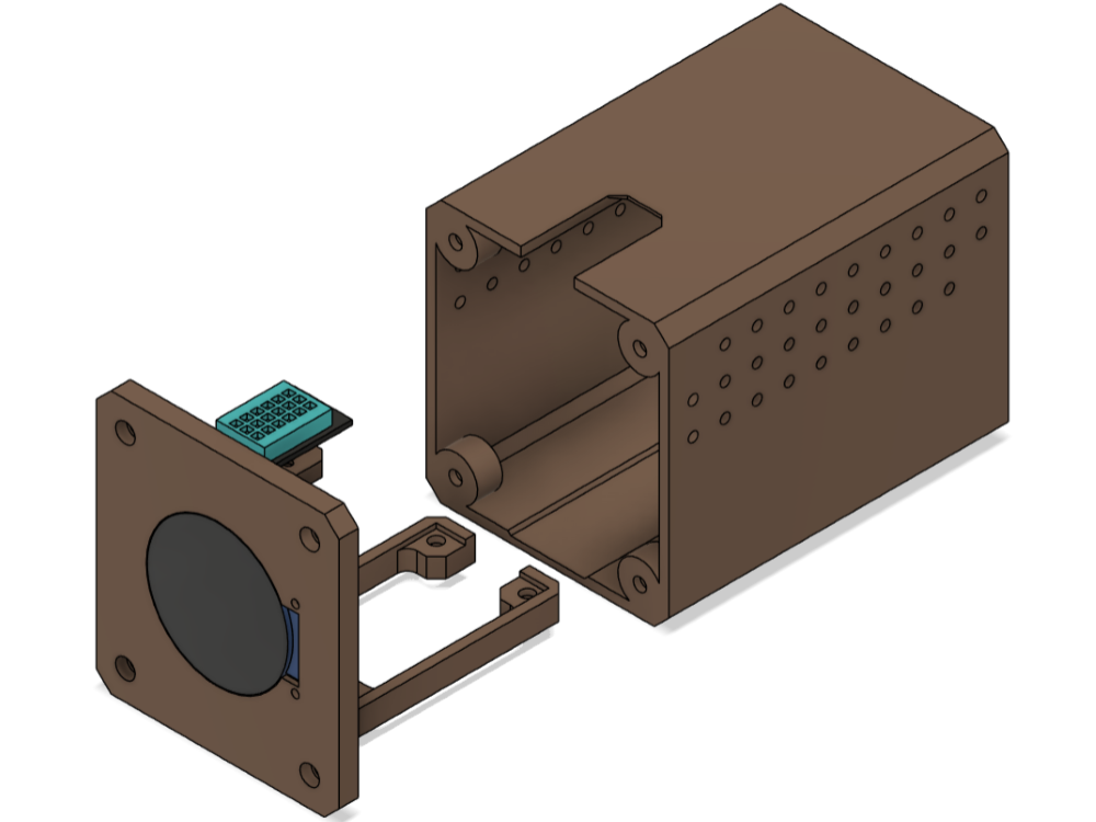
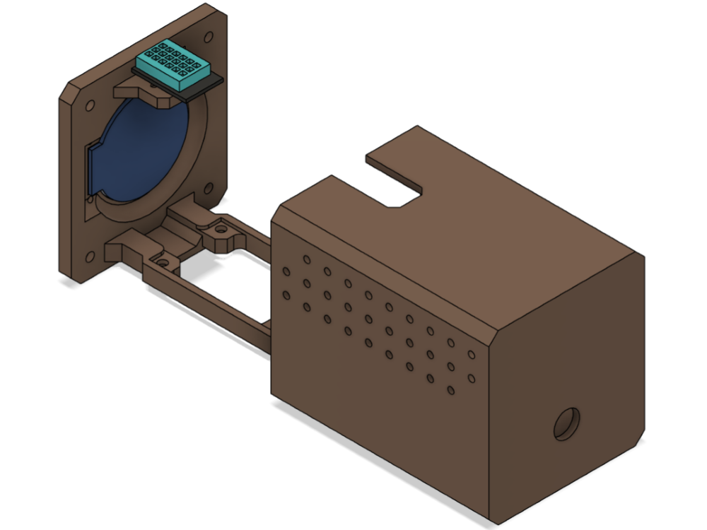
The Idea & Sketches
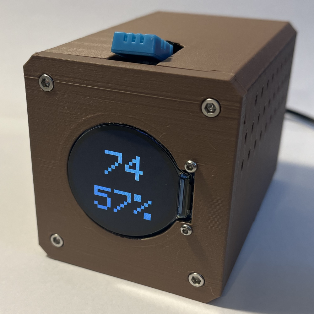
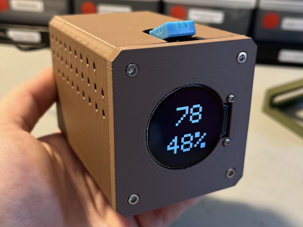
During the summer I had the idea to create a small device that continently displays the temperature of the room that you are in, and
I decided I wanted to develop that idea and create something out of it. To begin,
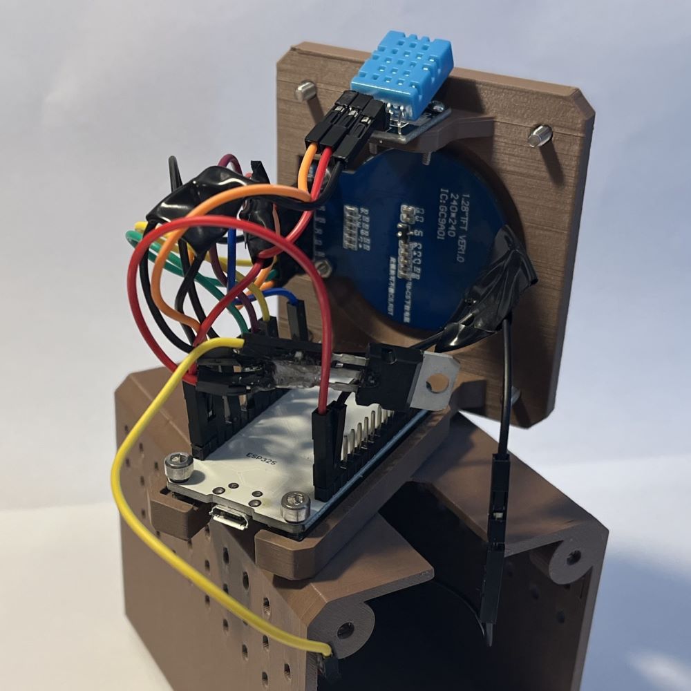
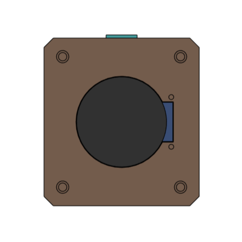
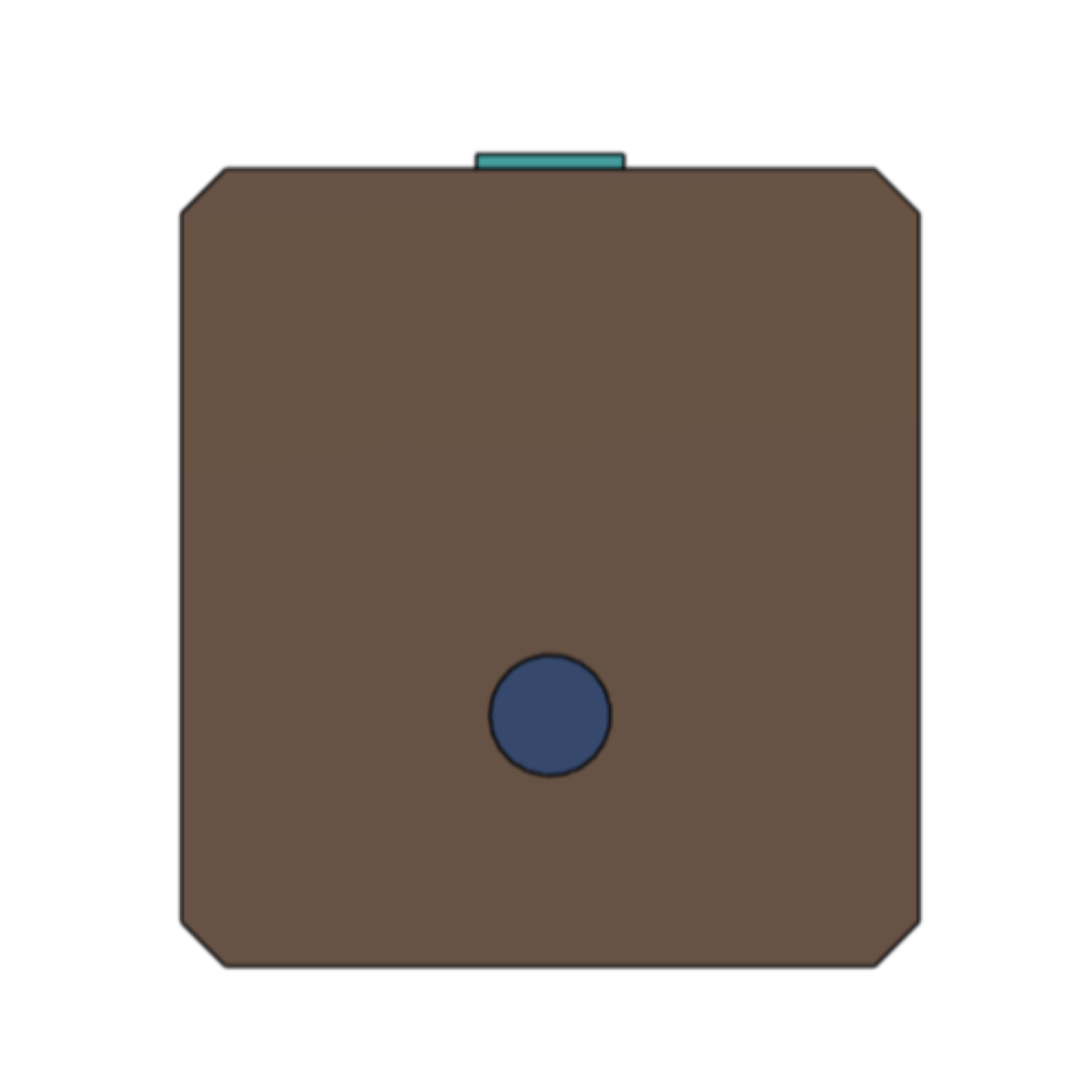
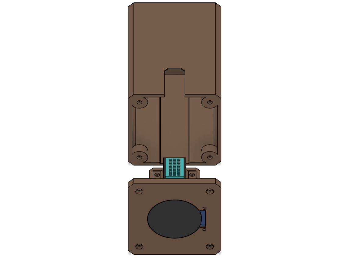
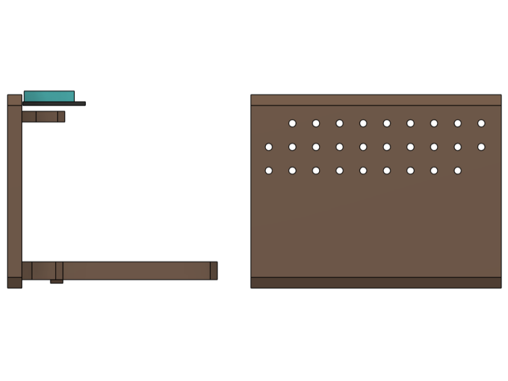
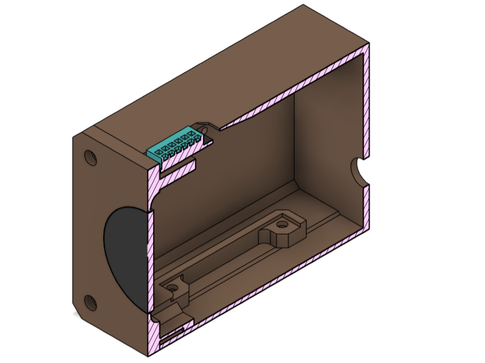
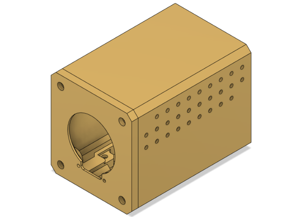
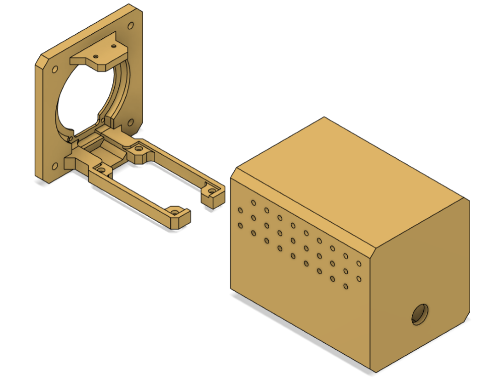
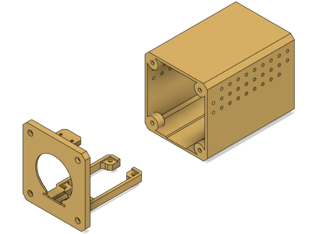
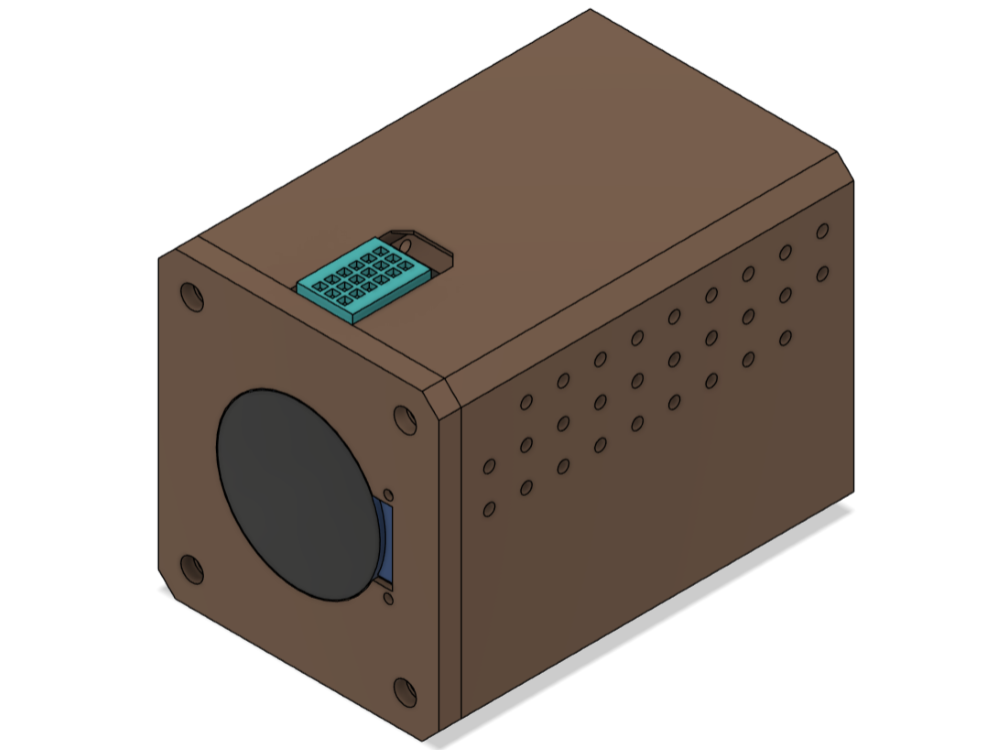
I developed a simple sketch of what I thought the device would look like as well as a general schematic for the electronics of the device.
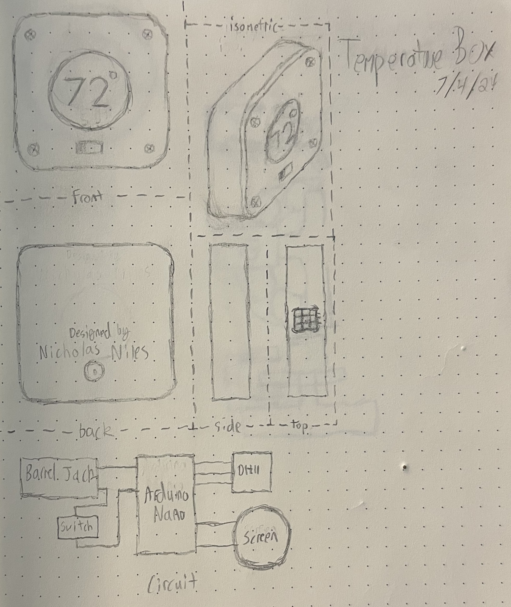 After sketching the general schematic of the electronics (seen at the bottom), I hopped into KiCad and got to work translating it into the program. I
used Fab Academy's Fab KiCad library to get a host of schematics I'd need for the project, it can be found
here. Note that I
chose to use an Atmel chip instead of a Nano from my original schematic once I was in the program.
For reference of pinouts on the 1614, I used somebody else's documentation found
here.
I ultimately got to the point of adding the screen to my schematic, at which point I realized the chip I selected may not be capable
of storing the libraries that might be needed to display the graphics I would need on the screen. I did lots of digging and
experimenting, with ChatGPT helping a lot, and ultimately found that the 1614 would thankfully meet my needs as the libraries and
program I wanted to upload would take about 6 kb of space and the 1614 has around 16 kb of flash storage on it.
 For code and wiring references, I used
this tutorial.
Using the pinouts provided on this tutorial for the screen I drew a custom symbol in KiCad for the screen:
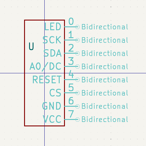 I then added this custom symbol to my schematic and then using this source
I compared where the pins were going on the Uno to correctly translate them to my chip. I came up with this schematic finally:
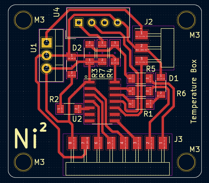
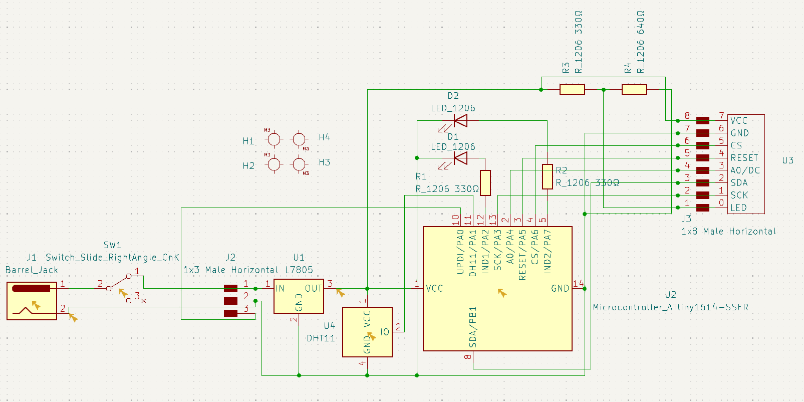 I then hopped into KiCad's PCB design tool and began routing traces between all my components, and it was very difficult. I unfortunately ended up having to add 3
0 Ohm resistors to get the job down to jump gaps on the board that were otherwise impossible, and I came up with this:
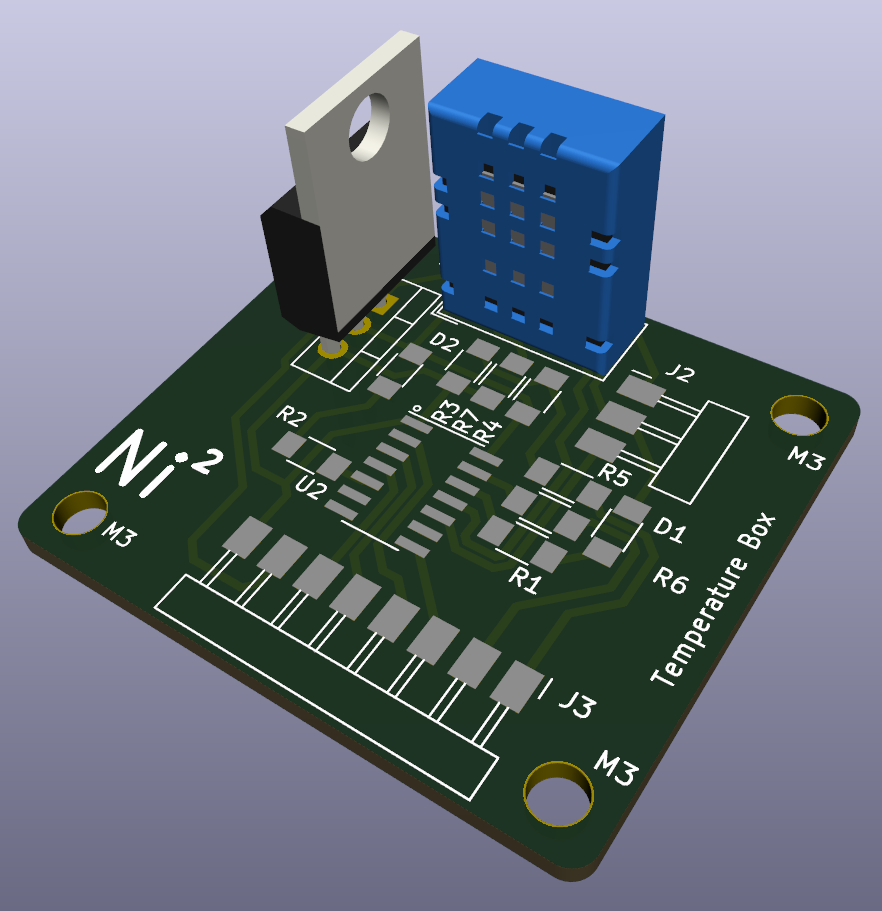
 And here is how it is going to look in 3D:
 I now developed a Bill of Materials (BOM) for the project, as seen below:
I also made note from here that I needed to have a resistor from
VCC to the IO pin of the sensor if I wasn't using the typical DHT11 module that is typically sold, so I implimented that
into my KiCad design as well. I also had to adjust the voltage divider resistances from 330 and 640 to 100 and 220 due to the former
being rarer values of resistance (640 specifically).
Overall the manufacturing of the PCB and parts total just under $40, though most of that is shipping so in bulk the cost is way lower to make these. I decided before I order everything I'd do a comprehensive electronics review to make
sure everything was designed correctly, so I did that next.
