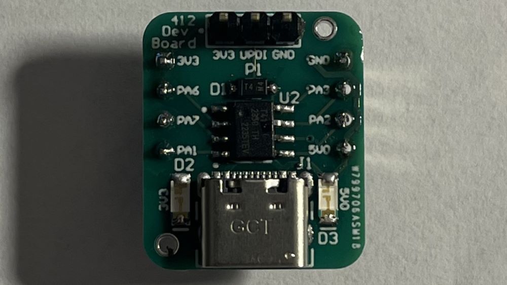
This board is designed to be an ultra-compact microcontroller Dev Board for prototyping of small and simple MCU-needing projects. It features a UPDI programming header and two additional headers for all GPIO pins of the MCU as well as power. It snaps right into the middle of a breadboard as well for ease of prototyping. It can be powered via the power pins on the device (at 5V or 3.3V) or via USB-C.
This project is sponsored by PCBWay, a wonderful and easy to use PCB manufacturer.
Below are videos demonstrating different features of the ATtiny412 Dev Board.
The video below shows me programming the chip on the board and blinking an LED at different speeds.
The video below shows the board outputting MCU UART data through an FTDI board to USB Serial on my laptop.
Below are photos showcasing the final schematic sections and printed circuit board design for the project.
Below is a table containing all of the parts as well as a link to the Digikey parts list.
Part Name | Count | Cost Per Part |
---|---|---|
ATtiny412 MCU | 1 | $0.58 |
1µF 1206 Capacitor | 3 | $0.12 |
1x4 2.54mm Male Header | 2 | $0.10 |
1x3 2.54mm Male Header | 1 | $0.10 |
Green 1206 LED | 2 | $0.23 |
USB-C Female Connector | 1 | $0.78 |
3.3V LDO | 1 | $0.22 |
1µF 1206 Capacitor | 1 | $0.08 |
SMD Diode | 1 | $0.11 |
5.1kΩ 1206 Resistor | 2 | $0.10 |
620Ω 1206 Resistor | 1 | $0.10 |
1kΩ 1206 Resistor | 2 | $0.10 |
Using the Device such as Pinouts or Setup is detailed below.
Below is information and necessary tables of pinouts for the device.
Pin Technical Name | Pin Name | Pin Info |
---|---|---|
USB-C | USB-C | USB-C Power (5V) |
P1 - 1 | 3V3 | MCU 3.3V |
P1 - 2 | UPDI | UPDI Programming Line |
P1 - 3 | GND | MCU GND |
P2 - 1 | GND | MCU GND |
P2 - 2 | PA3 | MCU PA3 / SDA (I2C) |
P2 - 3 | PA2 | MCU PA2 / TX (UART) |
P2 - 4 | 5V0 | 5V Power |
P3 - 1 | 3V3 | MCU 3.3V Power |
P3 - 2 | PA6 | MCU PA6 / SCL (I2C) |
P3 - 3 | PA7 | MCU PA7 |
P3 - 4 | PA1 | MCU PA1 / RX (UART) |
The device can be powered through multiple methods. The downward pin headers (P2 & P3) can have 3.3V or 5V power put to the respective power lines as input power to the device. Additionally, USB-C can be plugged in to power the board, or 3.3V can be plugged into the programming header. For programming, an Arduino Uno can be used, with the UPDI pin of the programming header attached to D6 of the arduino and the 3.3V and GND of the programming header attached to their equivalent pins on the Uno. For a detailed tutorial on programming this Dev Board from there, visit my Coil Gun Mk. 2 project page through that link, as it will show you how to program it step by step, with the only difference being that you select the 412 as the MCU target and not the 1614.
Challenges, What I Learned, and More.
A big challenge for me was keeping the UPDI programming line at 3.3V even though the programmer was outputting high signals at 5V to the device to program it. To resolve this and through research I learned about diode voltage clamping and applied that knowledge to this circuit to achieve a safe voltage range on the UPDI line.
In doing this project, much was similar to my other Dev Boards. I'd say this helped further develop my PCB design skills, mainly because of the compact size I was really shooting for, as well as teaching me the circuitry and technique of diode voltage clamping.
This project didn't have an inherit inspiration but rather was meant to give me another option in terms of MCU for prototyping future projects like my other Dev Boards.