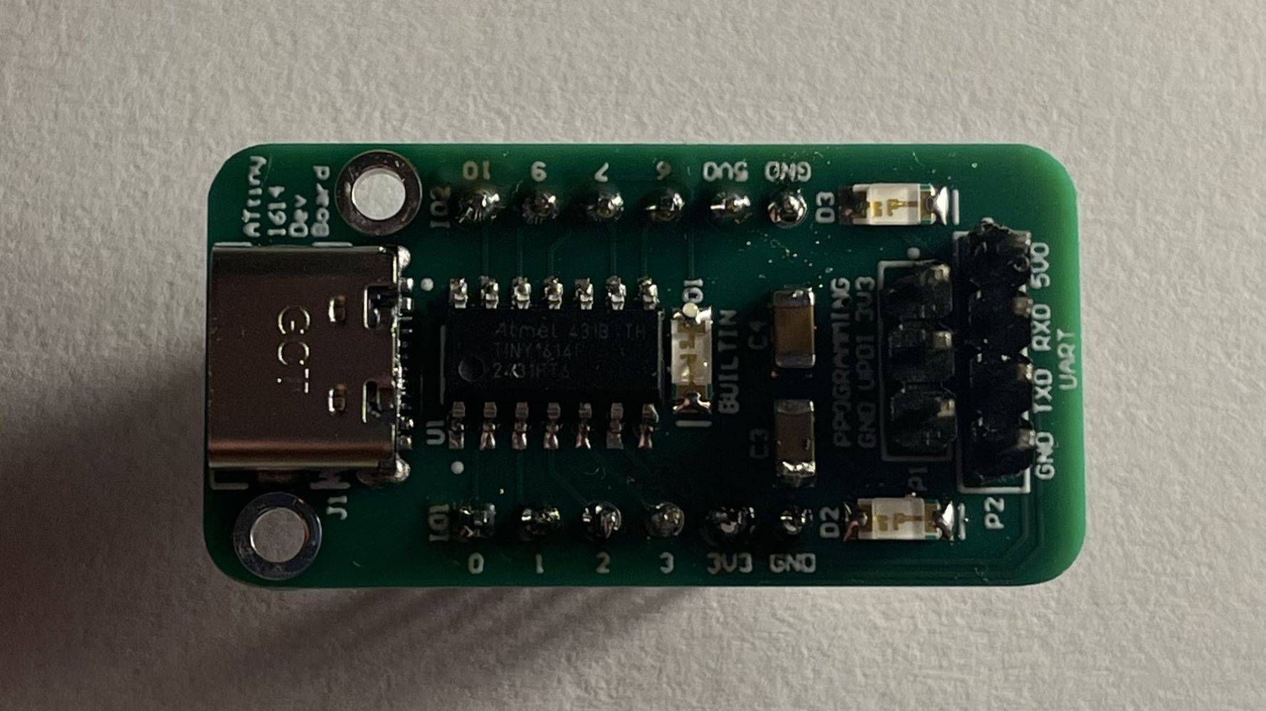
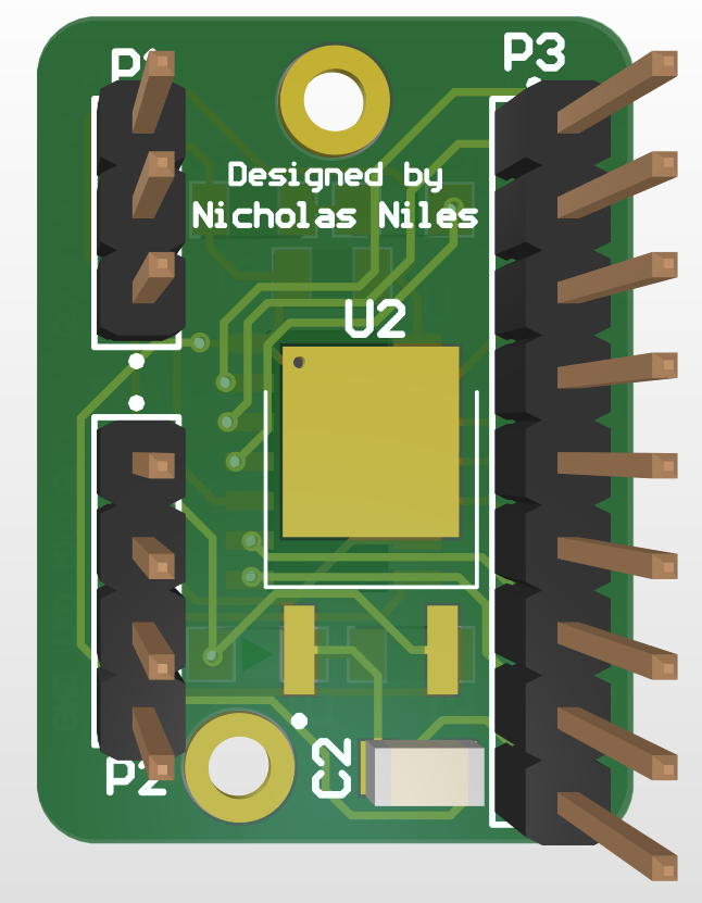
This PCB I designed, had manufactured, and soldered is a microcontroller dev board similar to my ESP32-C3 Dev Board. This board, instead hosting an ATtiny1614 chip, is likely to be the center of many projects I develop going forward. With programming via an Arduino Uno using the Arduino IDE and able to fit right into a breadboard, it makes a great and cheap microcontroller dev board for prototyping (and later in final layout) of projects.
This project is sponsored by PCBWay, a wonderful and easy to use PCB manufacturer.
Below are videos demonstrating different features of the ATtiny1614 Dev Board.
The video below shows me programming the chip on the board and blinking the LED at different speeds.
The video below shows the board outputting MCU UART data through an FTDI board to USB Serial on my laptop.
Below are photos showcasing the final schematic sections and printed circuit board design for the project.
Below is a table containing all of the parts as well as a link to the Digikey parts list.
Part Name | Count | Cost Per Part |
---|---|---|
ATtiny1614 Chip | 1 | $0.92 |
3.3V Regulator | 1 | $0.22 |
USB-C Female | 1 | $0.78 |
620Ω 1206 Resistor | 2 | $0.10 |
1kΩ 1206 Resistor | 2 | $0.10 |
5.1kΩ 1206 Resistor | 2 | $0.10 |
1µF 1206 Capacitor | 3 | $0.12 |
10µF 1206 Capacitor | 1 | $0.08 |
LED Green 1206 | 3 | $0.20 |
1N4148W-7-F | 1 | $0.11 |
1x4 2.54MM Male Header | 1 | $0.10 |
1x3 2.54MM Male Header | 1 | $0.10 |
1x6 2.54MM Male Header | 2 | $0.31 |
Using the Device such as Pinouts or Setup is detailed below.
Below is information and necessary tables of pinouts for the device.
Pin Technical Name | Pin Name | Pin Info |
---|---|---|
P4 - 6 | GND | Ground |
P4 - 5 | 3V3 | 3.3V Line |
P4 - 4 | 3 | PA7 of 1614 |
P4 - 3 | 2 | PA6 of 1614 |
P4 - 2 | 1 | PA5 of 1614 |
P4 - 1 | 0 | PA4 of 1614 |
P3 - 6 | GND | Ground |
P3 - 5 | 5V0 | 5V Line |
P3 - 4 | 6 | PB1 of 1614 |
P3 - 3 | 7 | PB0 of 1614 |
P3 - 2 | 9 | PA2 of 1614 |
P3 - 1 | 10 | PA3 of 1614 |
P2 - 4 | GND | Ground UART line |
P2 - 3 | TXD | 1614 Tx UART line |
P2 - 2 | RXD | 1614 Rx UART line |
P2 - 1 | 3V3 | 3.3V UART line |
P1 - 3 | GND | Ground line for programming |
P1 - 2 | UPDI | UPDI line for programming |
P1 - 1 | 3V3 | 3.3V line for programming |
With a board like this, you'll need to program the device. This needs to be done in a special way. See my Coil Gun Mk. 2 project page through that link, as there is an entire section dedicated to programming an ATtiny1614. Beyond that, the board operation is simple, and the pinouts are as seen below:
Challenges, What I Learned, and More.
A big goal and as a result challenge for this project was the size of the board. I really wanted to make the board as compact as possible while still maintaining integrity of signals, soldering pad size, and silkscreen readability. I had, luckily, worked with these chips before, so understanding the UPDI protocol and a lot of the schematic design wasn't very difficult. Ultimately I was able to get the size down a ton to a very compact board whilst still having easy access to all the pin headers and making it breadboard-compatible.
From this project I most certainly furthered my PCB design skills. I learned to improve previous designs as well, as this project's PCB has gone through multiple full redesigns since the original design, all to improve the compactness and signal integrity.
This board really didn't have much of an inspiration and was more a practical project for prototyping ease. I will say, however, that this project is definitely reminiscent of my work in Fab Academy, as I worked with this chip quite a bit, and even used it in my final project on a PCB. That work, which can be visited here, shows somewhat of an inspiration for this board, and also how far I've come.