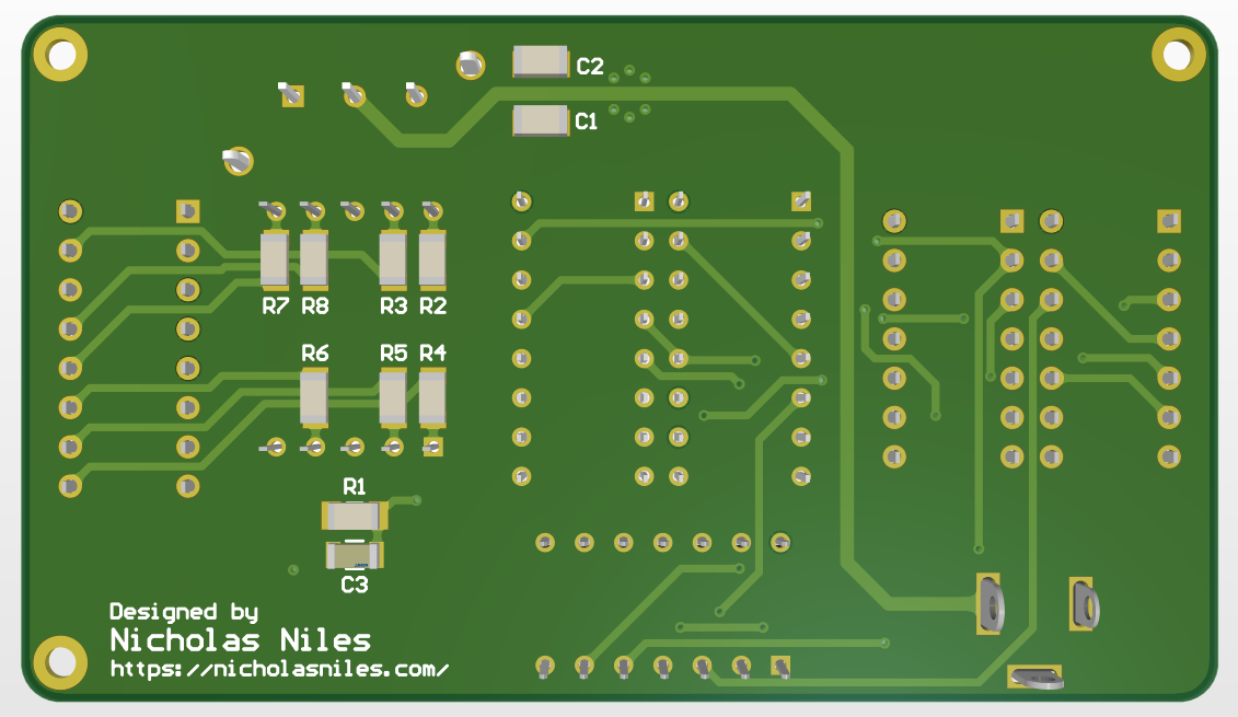
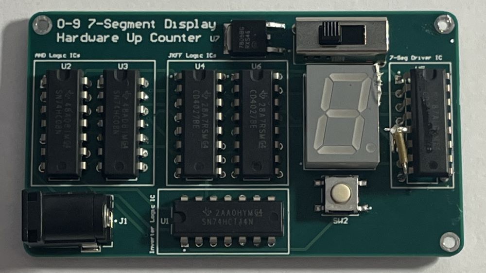
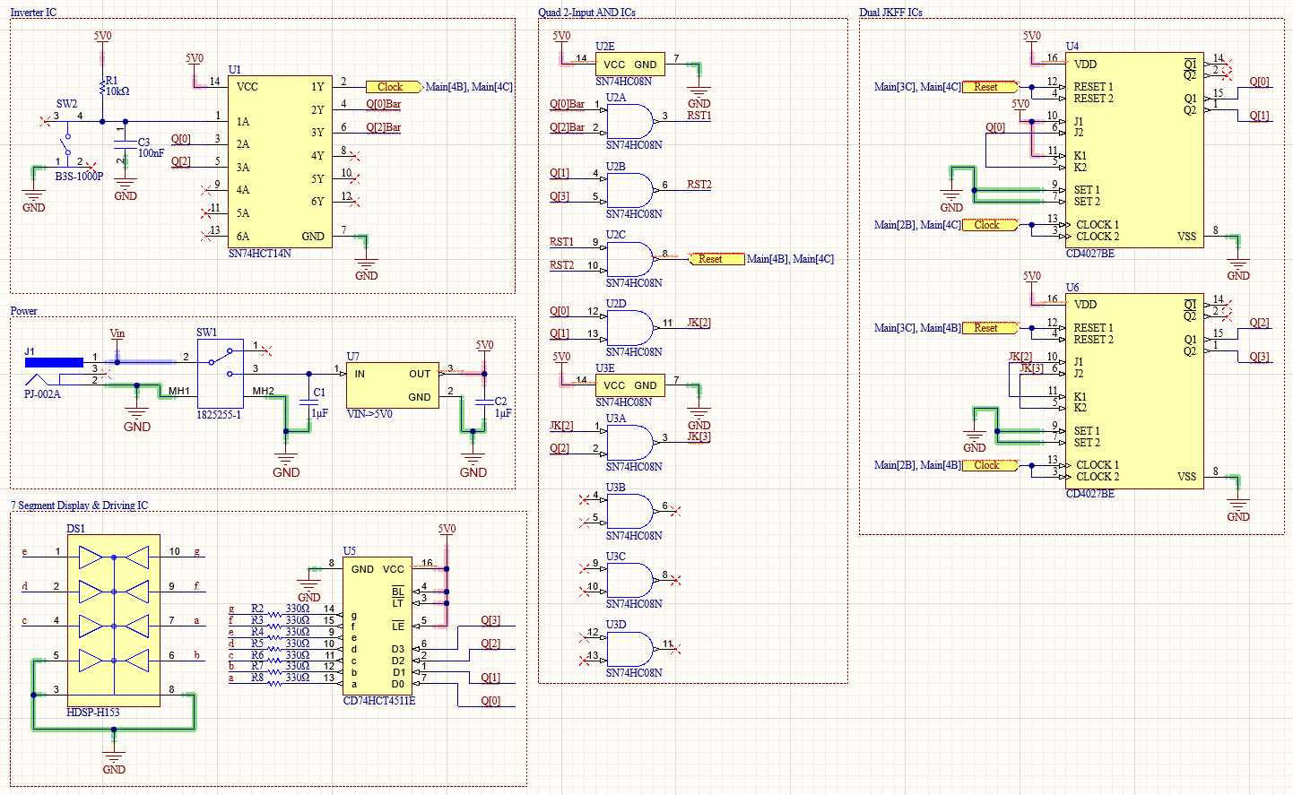
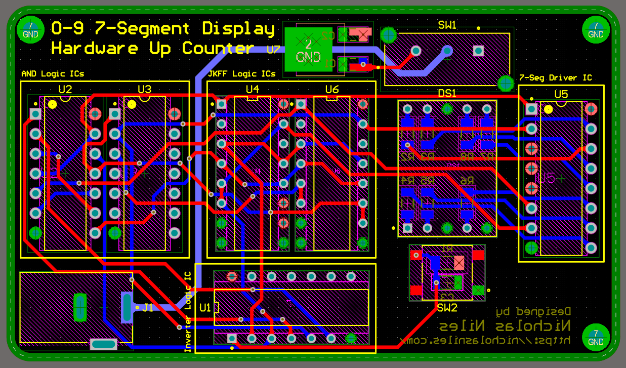
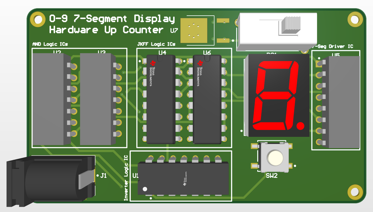
The 0-9 Digital Counter is a PCB I designed in Altium Designer that increments a 4-bit binary coded decimal (BCD) value stored in JK flipflops by 1 every time the user presses a push button, and it displays that counted value to a 7 segment display. It uses an asynchronous reset once the counter reaches 10 to set itself back to 0, and uses a serial-in parallel-out method of incrementing, storing, and outputting each bit of the 4-bit BCD number stored in the counter.
This project is sponsored by PCBWay, a wonderful and easy to use PCB manufacturer.
Below are photos showcasing the final schematic sections and printed circuit board design for the project.
Below is a table containing all of the parts as well as a link to the Digikey parts list.
Part Name | Count | Cost Per Part |
---|---|---|
0.1µF 1206 Capacitor | 1 | $0.08 |
1µF 1206 Capacitor | 2 | $0.12 |
PJ-002A Female Power Jack | 1 | $0.52 |
10kΩ 1206 Resistor | 1 | $0.10 |
330Ω 1206 Resistor | 7 | $0.10 |
SPDT Slide Switch | 1 | $1.66 |
SMD SPST Push Button | 1 | $0.76 |
SN74HCT14N (Inverter IC) | 1 | $0.66 |
SN74HC08N (AND IC) | 2 | $0.60 |
CD4027BE (JKFF IC) | 2 | $0.82 |
CD74HCT4511E (7 Segment Driver IC) | 1 | $0.95 |
5V SMD LDO | 1 | $0.49 |
7 Segment Display | 1 | $4.38 |
Using the Device such as Setup is detailed below.
The device just needs to be plugged in with 9V for example to the female power jack.
Challenges, What I Learned, and More.
A big challenge for this project was definitely both the initial breadboarding (getting it to work on bread boards before designing the PCB) and also matching all of the IC's family of logic (HC, HCT, or LS) by me having to find parts that work together online. The bread boarding of this project took about 3 days of on and off work, I ran into many strange glitches and logic issues, but ultimately prevailed. As for the logic family, I ultimately settled on HC / HCT (as these two are compatible) but had to replace my original 7 segment display driver IC (as it was originally of the LS family) which was rather challenging and took a lot of work. I even had to switch from a common anode display to a common cathode display simply because of this IC change, as I couldn't find a readily available active LOW output 7 segment driver not in the LS family.
In doing this project, I built on my knowledge I learned in my Digital Systems I class at Rochester Institute of Technology. A lot of this project was applying that knowledge but to physical hardware as opposed to uploading a logic circuit to a Field Programmable Gate Array, and that honestly helped give me more perspective on other ways to implement digital logic in hardware and about how I could use it going forward in future projects.
This project didn't really have an inspiration per say, it was more of just an idea I randomly had and kept building on as I developed the project further and further.