3.7V LiPo BMS

Circuit Board

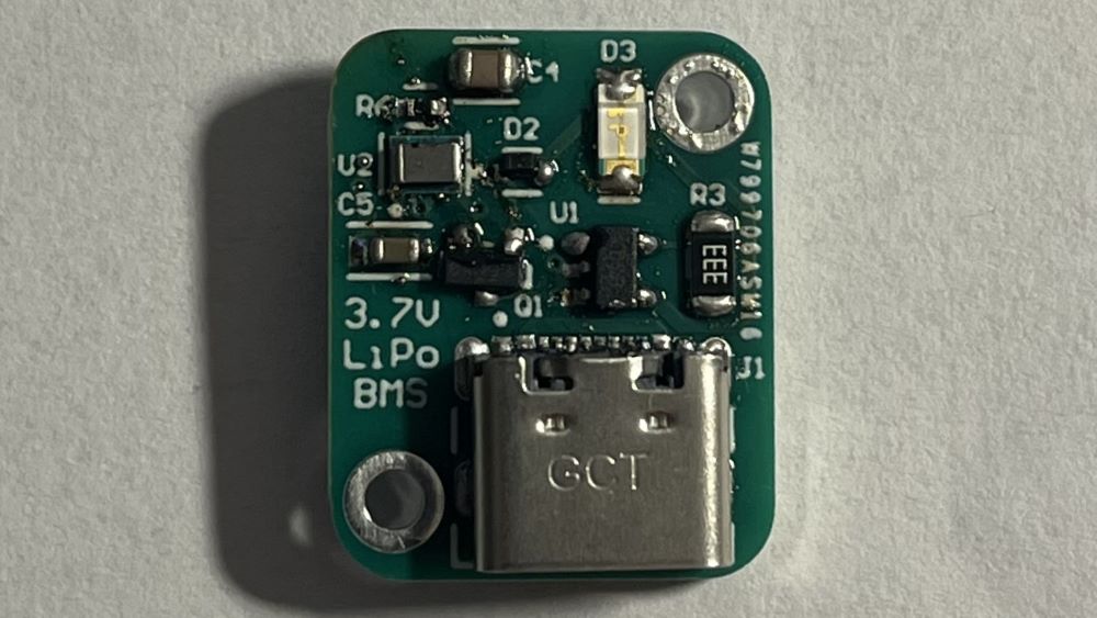
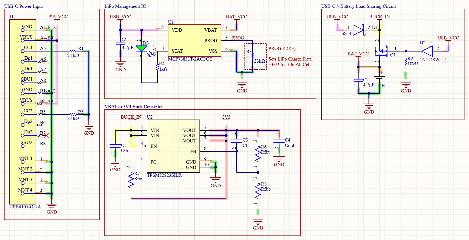
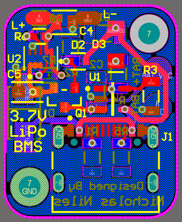
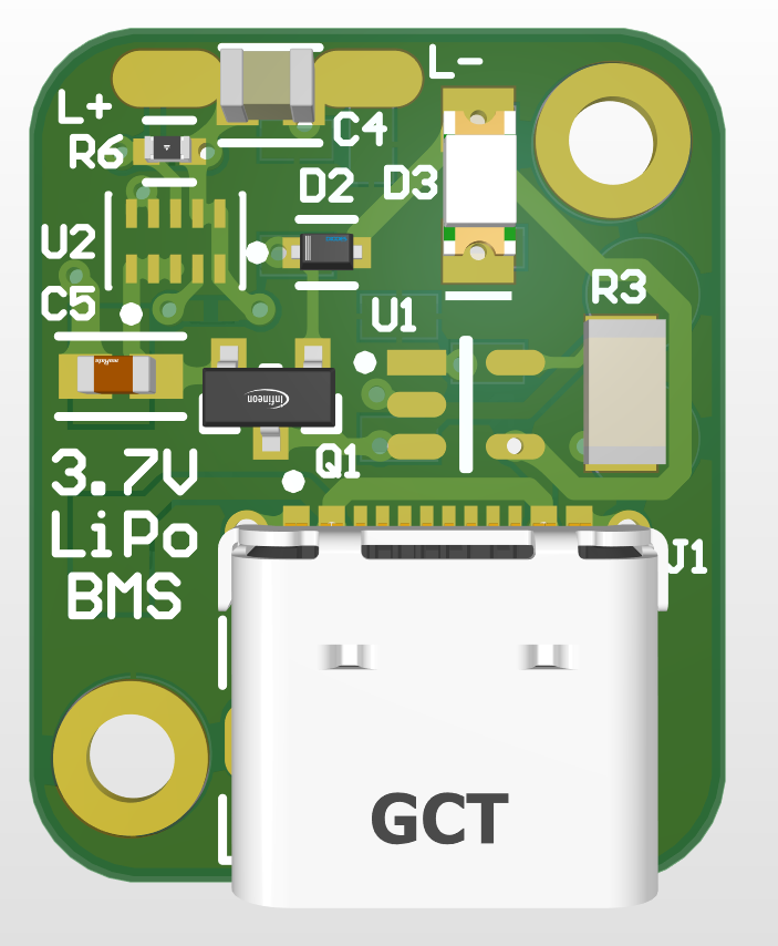
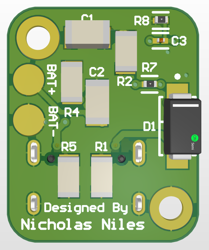
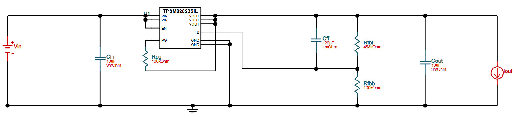
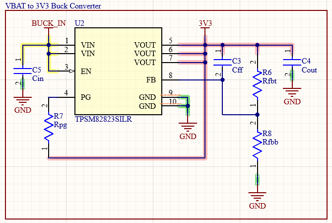
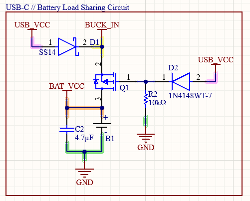
This PCB I designed manages the charging of a 3.7V LiPo battery. When powered by USB-C, the board is capable of load sharing, powering the load connected to the board in addition to charging the battery simultaneously. Seemlessly, the board, when unplugged, the board switches to powering the load off of the LiPo battery until the battery is depleeted. The board also has a WEBENCH-designed buck converter outputting 3.3V during both USB-C power and off the LiPo.

This project is sponsored by PCBWay, a wonderful and easy to use PCB manufacturer.

Skills Used

Altium

Ti WEBENCH

Demonstration Videos

Below are videos demonstrating different features of the 3.7V LiPo BMS board.

LiPo powering Load - Demonstration

The video below shows the BMS board powering the load via discharging the LiPo battery safely.

USB-C Load Sharing - Demonstration

The video below shows the load sharing capabilities of the BMS board when plugged in via USB-C. The board switches the load to be powered via the USB-C (when plugged in) instead of by the battery, and the battery, at the same time, charges from the USB-C as well. This forces the load to be powered via the USB-C instead of the battery that way the battery can be charged much faster whilst the device can still be used!

BMS Shutoff at Full Battery Charge - Demonstraiton

The video below shows the BMS shutting off and stopping charging the LiPo battery once the battery reaches full charge at around 4.2V. The indicator light (green LED) turns off once the battery is fully charged, as shown in the video.

Final Schematic Design & PCB Layout

Below are photos showcasing the final schematic sections and printed circuit board design for the project.

Entire Schematic

PCB 2D View

PCB 3D View - Front

PCB 3D View - Back

Bill of Materials (BOM)

Below is a table containing all of the parts as well as a link to the Digikey parts list.

Part Name Count Cost Per Part
USB-C Female Connector 1 $0.78
MCP73831T-2ACI/OT 1 $0.76
TPSM82823SILR 1 $2.96
5.1kΩ 1206 Resistor 2 $0.10
4.7µF 1206 Capacitor 2 $0.18
Green SMD LED 1 $0.23
1kΩ 1206 Resistor 1 $0.10
33kΩ 1206 Resistor 1 $0.10
SS14 1 $0.29
1N4148WT 1 $0.12
10kΩ 1206 Resistor 1 $0.10
IRLML6402TRPBF 1 $0.40
10µF 0603 Capacitor (GRM188R60J106ME84D) 1 $0.37
120pF 0201 Capacitor (GRM033R71E121KA01D) 1 $0.10
10µF 0805 Capacitor (C0805C106K8PACTU) 1 $0.13
100kΩ 0402 Resistor (CRCW0402100KFKED) 2 $0.10
453kΩ 0402 Resistor (CRCW0402453KFKED) 1 $0.10

Using the Device

Using the Device such as Pinouts or Setup is detailed below.

Device Pinouts

Below is information and necessary tables of pinouts for the device.

Pin Technical Name Pin Name Pin Info
USB-C Female Port USB-C USB-C Port for Power
BAT+ SMD Pad Battery+ Positive Battery Terminal
BAT- SMD Pad Battery- Negative Battery Terminal
L+ SMD Pad Load+ Positive Load Terminal
L- SMD Pad Load- Negative Load Terminal

Setting Up & Using the Device

Using the board is really easy. Once all the components are soldered on, simply connect the positive and negative terminals of the LiPo battery to the SMD solder pads on the bottom side of the board, and wire the load to the SMD solder pads on the top of the board labled L+ and L-. From there, simply plug in the board to USB-C to charge, or let it run off the LiPo! It's that easy!

Development Documentation

Challenges, What I Learned, and More.

Challenges

This board was a huge challenge in a lot of ways. In this board I utilize a ton of components and concepts that I've never worked with before, so there were plenty of thngs that could've gone wrong. Things like implimenting a WEBENCH buck converter design, designing the USB-C load sharing with diodes and MOSFETs, and properly laying out the peripherals for the charging IC so that it would properly charge the battery. BMSs are very complicated and I've wanted to work on this idea for a while but was hesitant because of all of these unknowns and new concepts I'd need to use.

What I Learned

This project honestly taught me tons. The biggest thing was furthering my understanding of LiPo batteries: how they work, how they charge, and how they discharge. I also fully developed my own custom-tailored buck converter using WEBENCH, which taught me a lot about buck/boost converters and advanced my knowledge with using the tool. I had to go through many different designs that WEBENCH provided for my custom needs to find the perfect buck converter as a lot of the parts the provided circuits used were unavaliable on DigiKey.

Inspiration

This board had no particular inspiration. I had been wanting to develop a LiPo BMS for a while but was hesitant because of the complexity. I suppose I was inspired by its potential uses, as I hope to make a wristwatch powered by this device, and I also know there are plenty of other applications I can use this for in future projects!

Additional Documentation

Specific feature breakdown, design choice explanations, and more.

WEBENCH-Designed Buck Converter

To make an efficient and well-designed buck converter is rather difficult. For this, I used Texas Instrument's WEBENCH tool online, which allows you to set specs for the buck converter design you want and it spits out a corresponding circuit for your needs. For me this was perfect, as I knew my Vin would be clamped to the battery min and max voltages and also the USB-C voltage, so a range of 5V down to 3.5V. With this data plugged into the tool I looked through the provided designs until I settled on the TPSM82823SILR IC and its accompanying peripheral circuitry as it fit my needs perfectly. It met the voltage/current draw needs of mine as well as all of its parts were avaliable online and the total size of the circuit was small. The parts for this buck converter are listed on the DigiKey list further up this page and in the Altium schematic files if you are interested.

The WEBENCH-Provided Schematic

Buck Converter Circuitry in my Altium design

USB-C Load Sharing Design

The USB-C load sharing is designed to seamlessly transition the load from being powered by the battery to being powered by USB-C or vice versa. This is done via the circuit shown below. When not plugged in to USB-C, the P-channel MOSFET allows current to flow from the LiPo battery to the buck converter then to the load. That current is also unable to leak to the USB-C port by accident as a Shottky diode from USB-C VCC prevents reverse current to flow there. Additionally, a 10kΩ pull down resistor on the MOSFET gate line pulls the gate to ground when no USB-C voltage is applied to prevent the gate from floating. The MOSFET, being P-channel, allows current to flow when the Vg < Vs by Vt (voltage gate < voltage source by voltage threshold). Therefor, when no voltage is applied at USB-C VCC (i.e. no USB-C plugged in and MOSFET gate is pulled to ground via pull down resistor) then current can flow from the LiPo to the load. On the other hand, when USB-C power is received (the device is plugged in), the LiPo will be charged and the load will be powered independetly of the LiPo. In that case, Vg > Vs, so the P-channel MOSFET prevents flow between source and drain, preventing discharge of the battery. Additionally, the Shottky diode then allows the USB-C VCC to flow to the buck converter. As a result, the LiPo charges and the load is powered, both done independetly, so the load is no longer drawing charge from the battery. This allows for faster and safer charging of the LiPo. The image below, as mentioned, showcases the circuitry that makes this possible.

Load Sharing Circuitry

3.3V Output Choice

I chose the buck converter to output a steady 3.3V for a good reason. 3.3V is the standard for all the microcontrollers I use (ESP32, Atmel chips), and since most of my projects revolve around the use of a microcontroller, this is the perfect voltage, as I can power my microcontroller directly off of the buck converter without the need for an inefficient LDO.