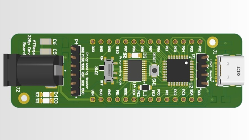
ATMega328PB Dev Board
Circuit Board
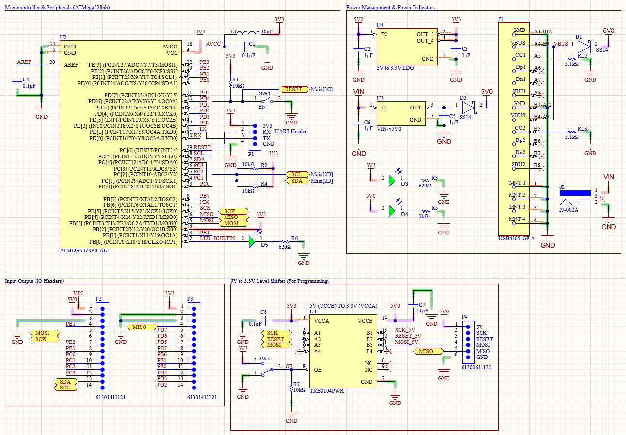
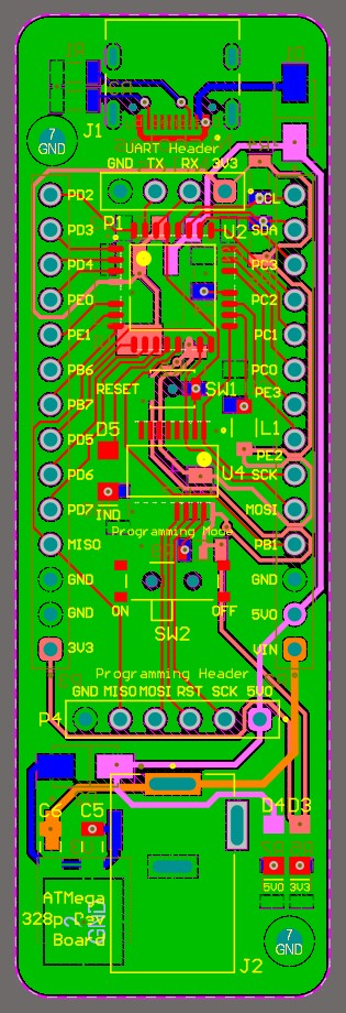
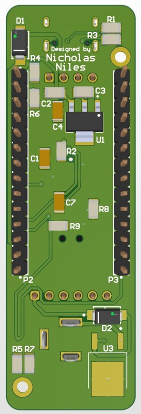
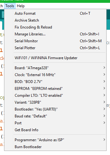
This board is a microcontroller PCB intended for project prototyping. I designed the board in Altium with this in mind. The MCU, the ATMega328PB, runs at 3.3V, and is programmed via SPI at 5V. A level shifter protects 3.3V SPI lines allowing for a 5V programmer to be used. This board is on the beefier side of the Atmel MCU catalogue, and as a result is a board designed for larger projects or ones with more complex code and libraries.
This project is sponsored by PCBWay, a wonderful and easy to use PCB manufacturer.