Here is a video demonstrating the device (The breadboard version, as the PCB Thermistor is much more precise and hard to demonstrate flipping on video) and what it does as well as a picture of it and the final circuit schematic from Altium Designer:
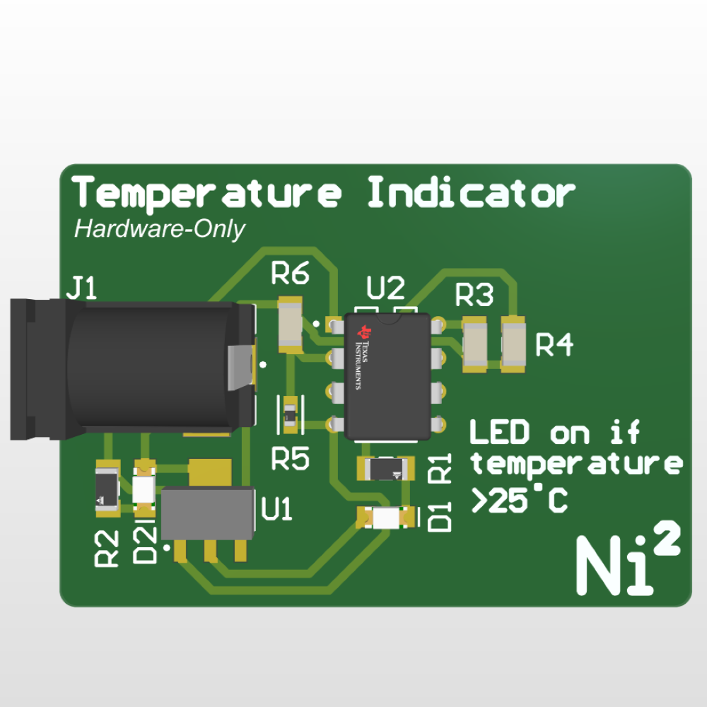
A 3D rendering of the PCB design for this project, which looks identical to the final soldered version.
Additionally, here is the BOM for the project, specifically the breadboard version:
Part Name | Count | Cost Per Part | Part Link |
---|---|---|---|
103JG1K Thermistor | 1 | $0.54 | Link |
LM311P Comparator | 1 | $0.85 | Link |
10kΩ Resistor | 3 | $0.10 | Link |
470Ω Resistor | 1 | $0.10 | Link |
LED | 1 | $0.27 | Link |
L7805 5V Regulator | 1 | $0.48 | Link |
Female Barrel Jack | 1 | $0.40 | Link |
Breadboard | 1 | $2.90 | Link |
And the total cost of the project comes out to only $5.84.
Start to finish of how I developed the device.
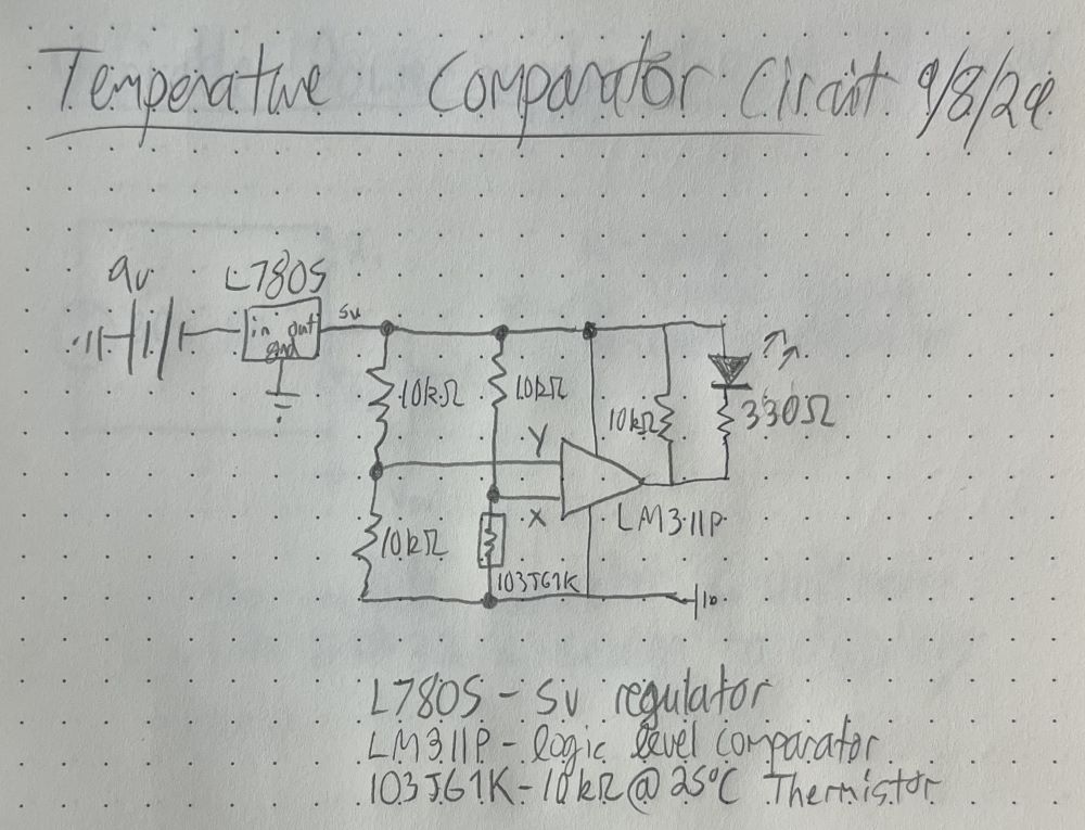
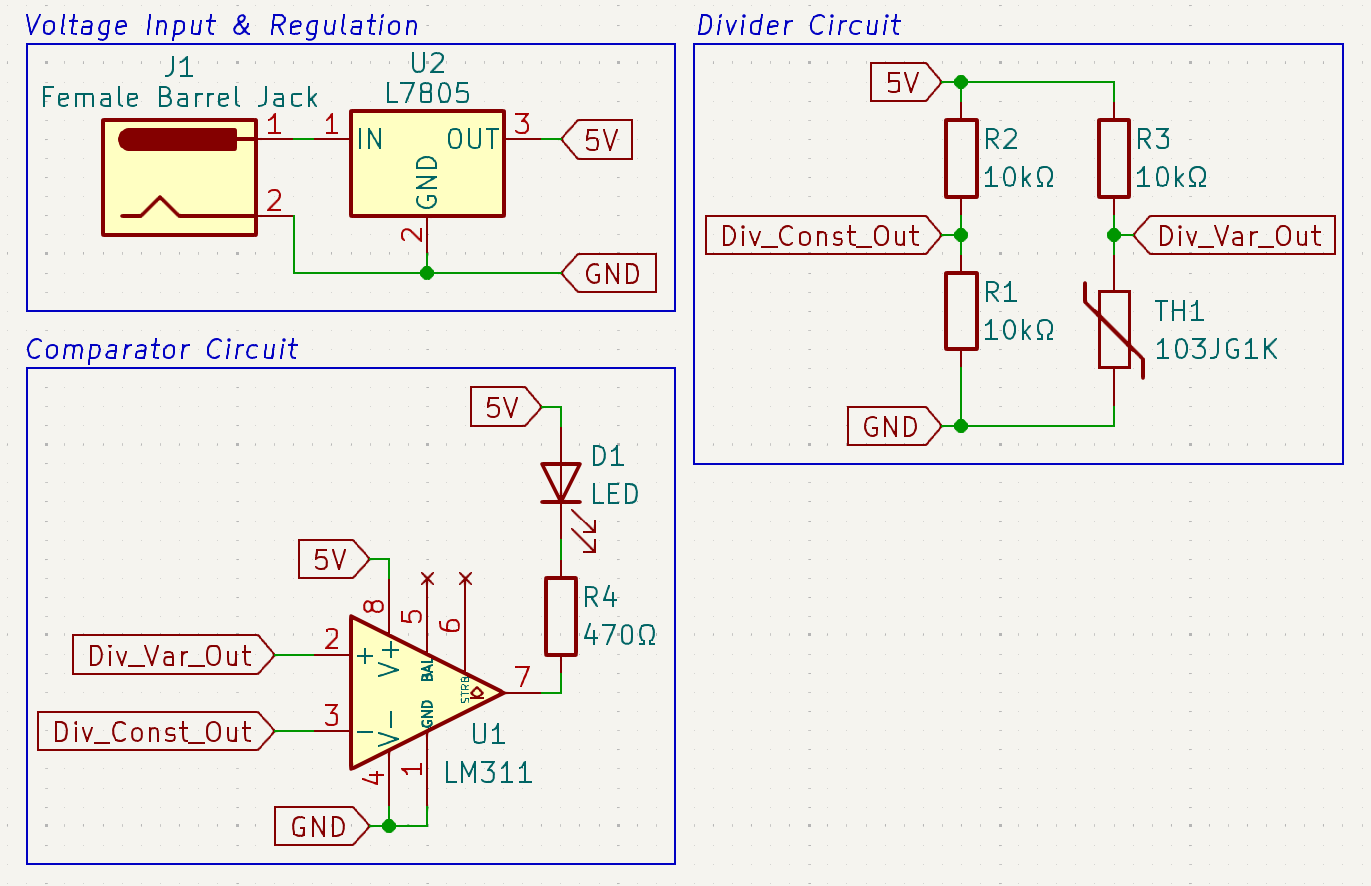
The idea to work on this circuit came from the book The Art of Electronics by Paul Horowitz and Winfield Hill. The book features a simple thermistor/comparator circuit to turn an LED on. While I like their approach, not only did I want to target a different temperature for the LED turn on, I also wanted to use different parts for both the comparator and thermistor. I chose to change my constant resistors to 10kΩ to target a temperature of 25°C instead of what they aimed for. The circuit itself, for some context, works as two separate voltage dividers both connected to a comparator, a comparator which also has the cathode of an LED attached and a 5V line attached. One voltage divider is held constant, and the other divider's second resistor is a thermistor before reaching ground. As I'm inputting a voltage of 5V to both dividers, the constant divider, which consists of two 10kΩ resistors, will output a constant 2.5V. This then goes to the Y terminal of the comparator. A second divider, consisting of a 10kΩ resistor and then the thermistor, will output a variable voltage to the X terminal of the comparator. When the comparator reads X's voltage to be less than Y's, it will pulls the LED's cathode connected to it to GND, thus allowing the LED to turn on. In my case, I want to have a thermistor that reads more than 10kΩ in conditions of greater than 25°C, that way the LED will only turn on if the temperature is greater than 25°C (As then the second divider's second resistor will be greater than 10kΩ, thus outputting a lower voltage from the divider, then pulling the LED to ground). A notable modification I made to the circuit is to have a 5V L7805 regulator to bring down the input voltage from what will likely be a 9V battery to acceptable levels for the comparator and other components.
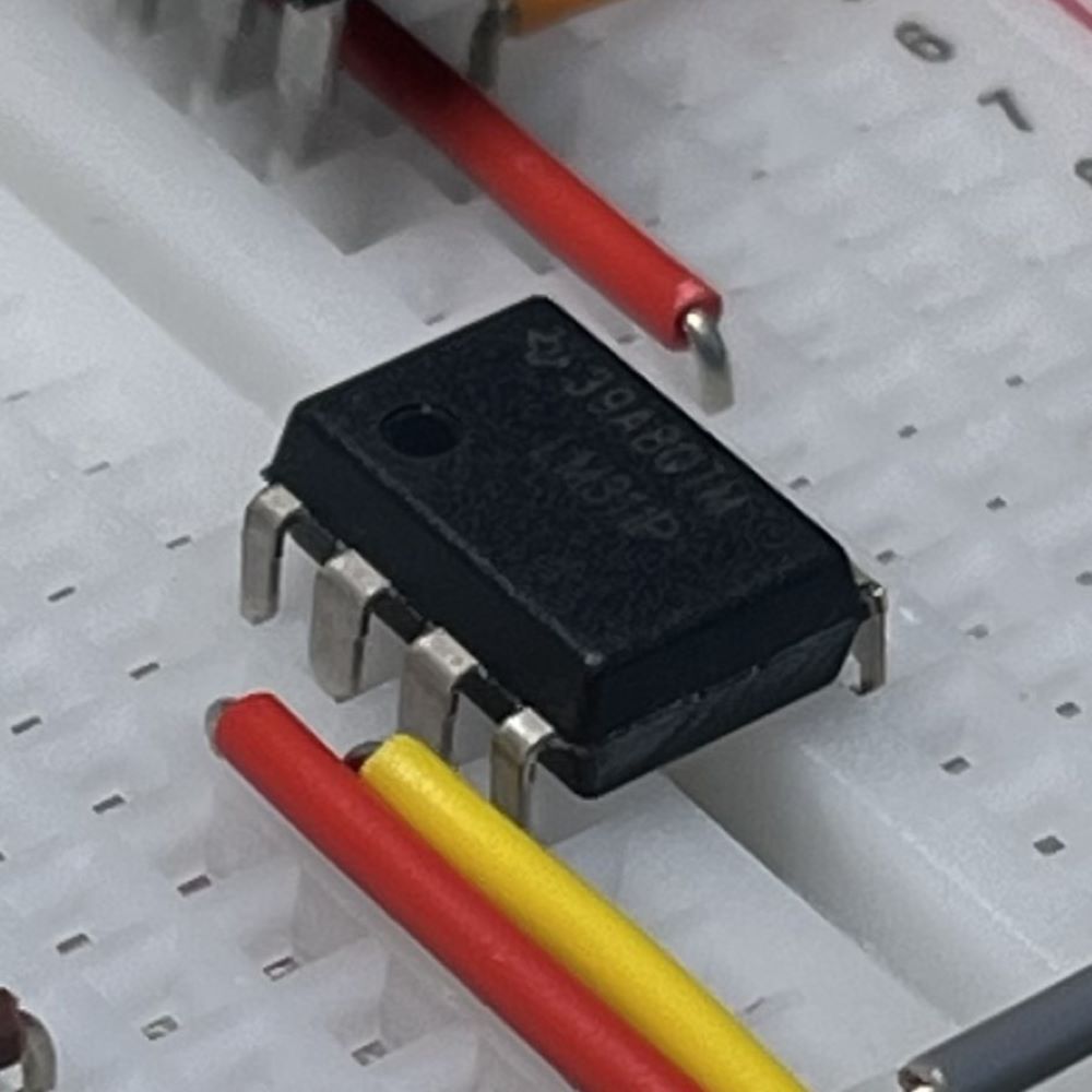
Using a similar layout to that presented in the book, I drew up the schematic in my notebook. I then went to Digikey, where I source my parts from, in order to find parts that would work as alternatives. For my thermistor, I chose the 103JG1K. Reading through its datasheet, which you can find here, I found that this particular thermistor acts as a 10kΩ resistor when in conditions 25°C, with its resistance increasing more as the temperature goes above that. I wrote that into my schematic drawing and continued on. When looking for comparators, I specifically wanted one that was through-hole and also that would work at the current and voltage levels I planned to operate at. I landed on Texas Instruments' LM311P comparator, an IC that met all the conditions I needed for my circuit. I added the part number into my schematic and ordered the necessary parts from Digikey. My final schematic can be seen in the attached image.
Now that I had the part numbers and full schematic drawn I decided to hop into KiCad and draw out the circuit. Key differences between the drawn schematic and the KiCad schematic I developed were as follows: Replaced the 330Ω resistor with a 470Ω as I have that on hand, and also X and Y were changed to the + and - which was embedded into the symbol I am using in KiCad. I used this source as a helpful reference for wiring up the LM311P correctly, as the KiCad schematic includes pins not mentioned in the book. All-in-all, I finished the KiCad schematic and after some organization the final schematic is attached here.
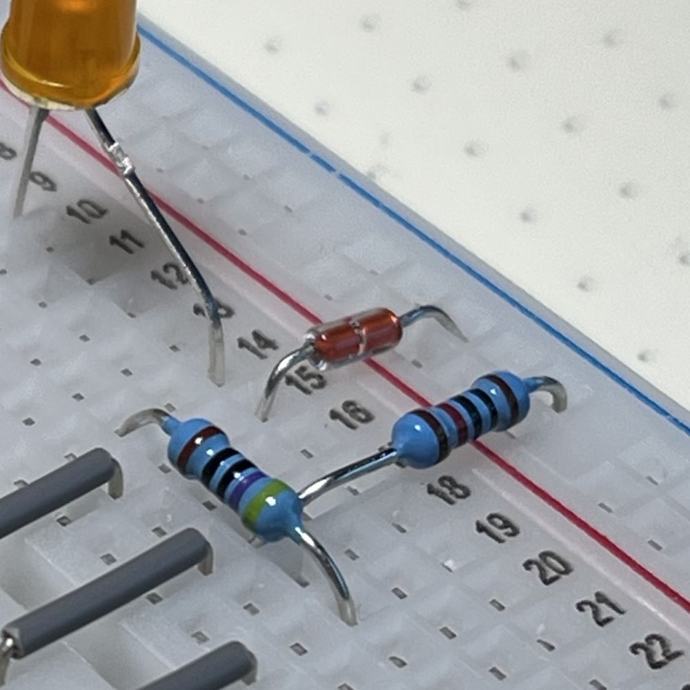
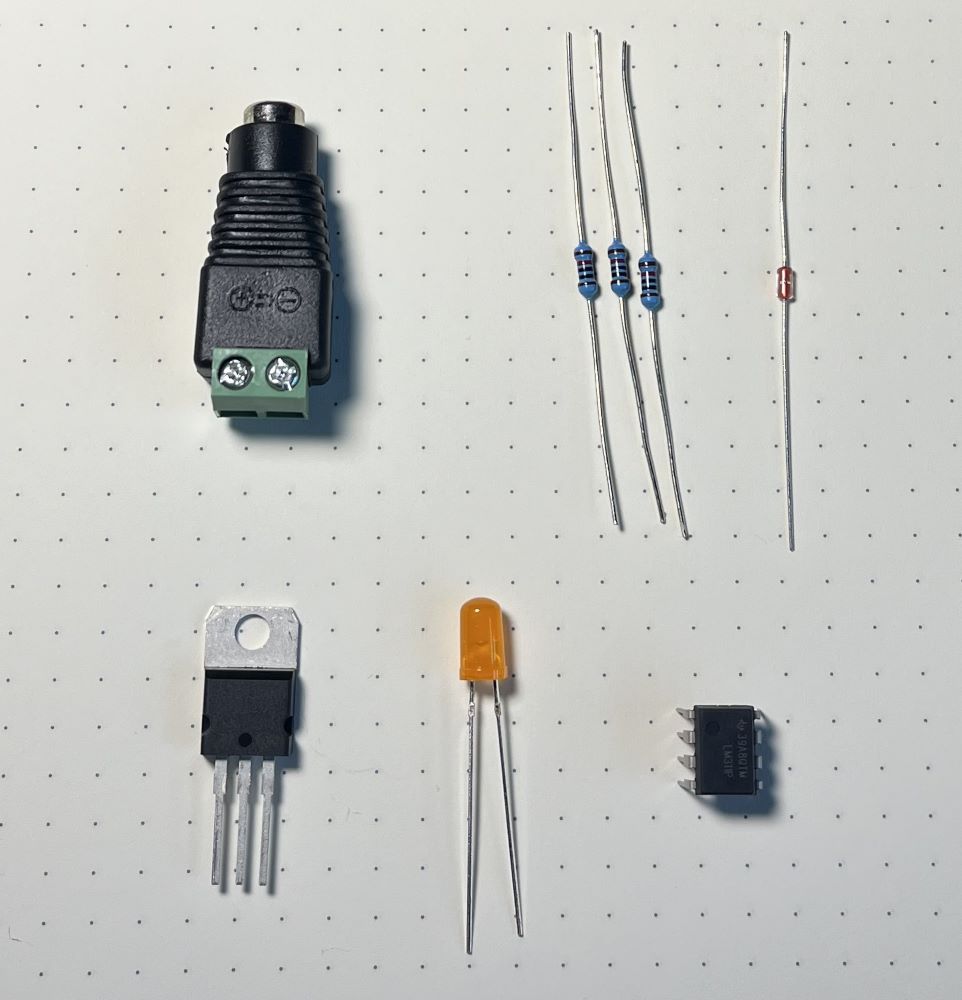
Armed with research, my Digikey order, and a drawn schematic, I was ready to finally build the device on a breadboard. I assembled all the parts before building
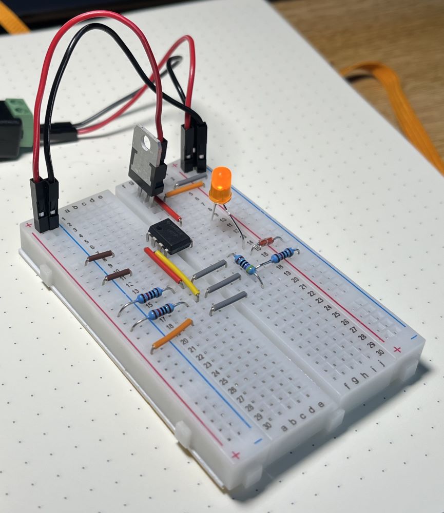
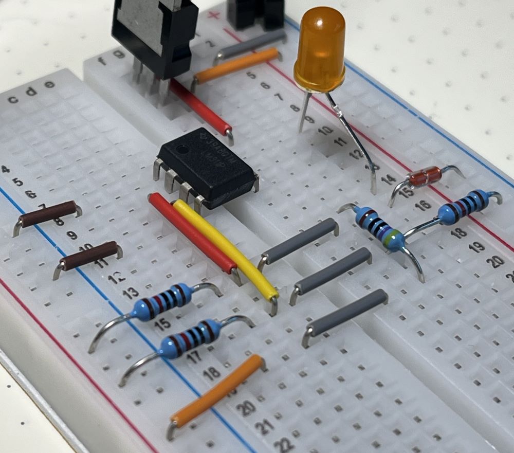
and then began building. Note that the 470Ω resistor is missing from this photo. Once I put the circuit together, and after some troubleshooting, I finished the build and everything worked as intended! I had an issue with a reference image I was using to do the pinouts as it was layed out incorrectly and was causing me to wire everything wrong, but as I said, after some troubleshooting, everything worked!
Though the project is complete and working, I decided to take the project and move over to Altium Designer from KiCad and design an actual PCB for the project. I hopped into Altium Designer, started a fresh project, and recreated my KiCad schematic in Altium. The schematic came out like this:
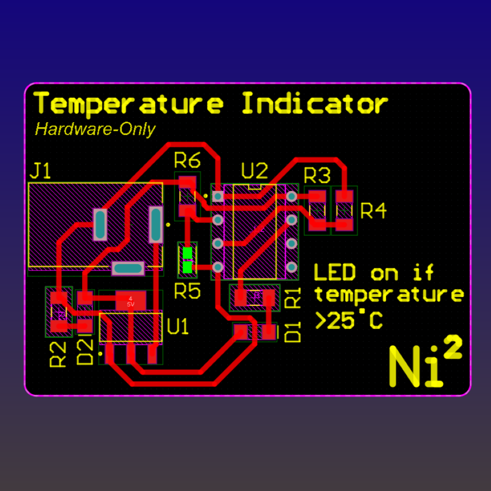
From here, I imported my design into Altium's PCB design tool, and placed components and routed my traces. My final PCB came out as follows:
Once both my manufactured boards and parts shipped, I went through and soldered all the parts onto the board. The thermistor in particular was the hardest part, as it was TINY. Ultimately, once soldered, I tested the project running it off a 9V battery, and it worked. One thing, different to the breadboarded version, was that this thermistor has a much tighter tolerance and accuracy, and also takes much longer to heat and cool. This is fine as I put it in the fridge and heated it up with my soldering iron to find that it was working, but it made it hard to create a demonstration video hence why I kept the breadboard video as the final product showcase. However, all in all, it worked!