Flight 282 Puzzle

Device

A puzzle I developed for my position as Puzzle Engineer at Escape Tactic, LLC. This puzzle required players to place 4 plane-shaped puzzle pieces in the right spots to trigger both a 4 digit code and 4 letter code to appear to continue the escape room. I designed, milled, and surface-mount soldered my own PCB to run the puzzle, including an ATtiny1614 microcontroller and i2C protocol for the 7 segment displays.
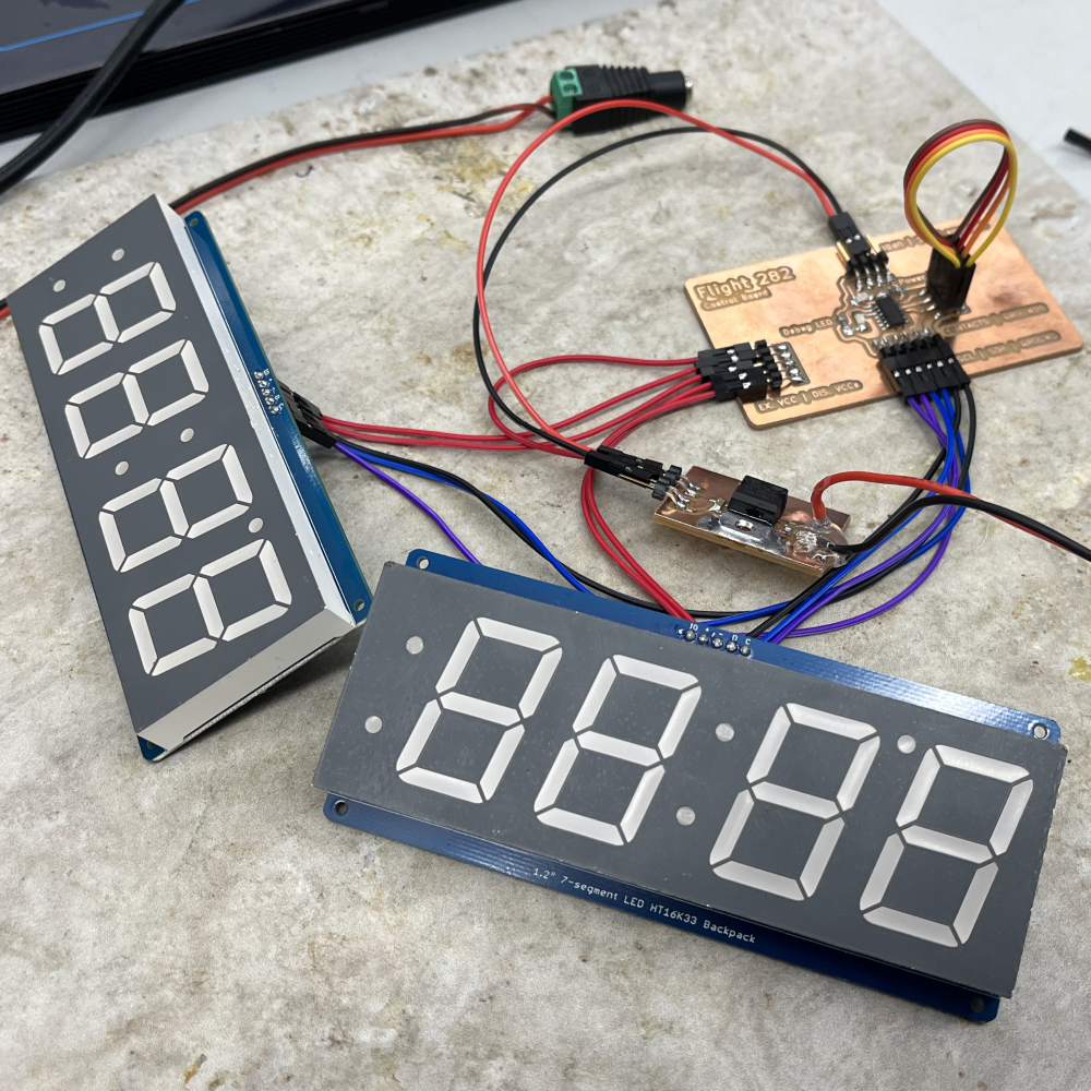
A shot of all the final electronics in one place, showing the main board (upper right), power regulation board (board below the larger board), and the dual seven segment display setup to the lower left.

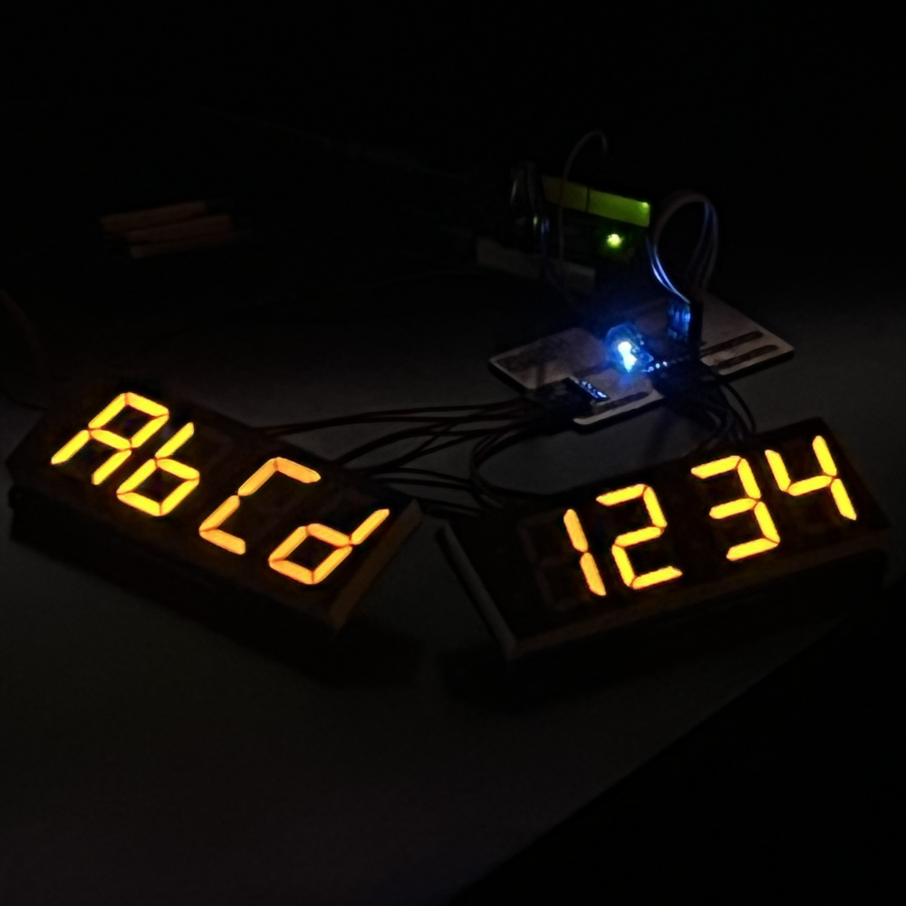
A shot of both screens displaying their codes in the dark. Codes only show once the players arrange all four puzzle pieces in the correct order. The codes help them progress to the next puzzle in the escape room.

Skills Used

KiCad

Fusion 360

C++

Milling PCBs

Advanced Circuitry

Finished Product

Here is a video demonstrating the device and more information on the electronics:

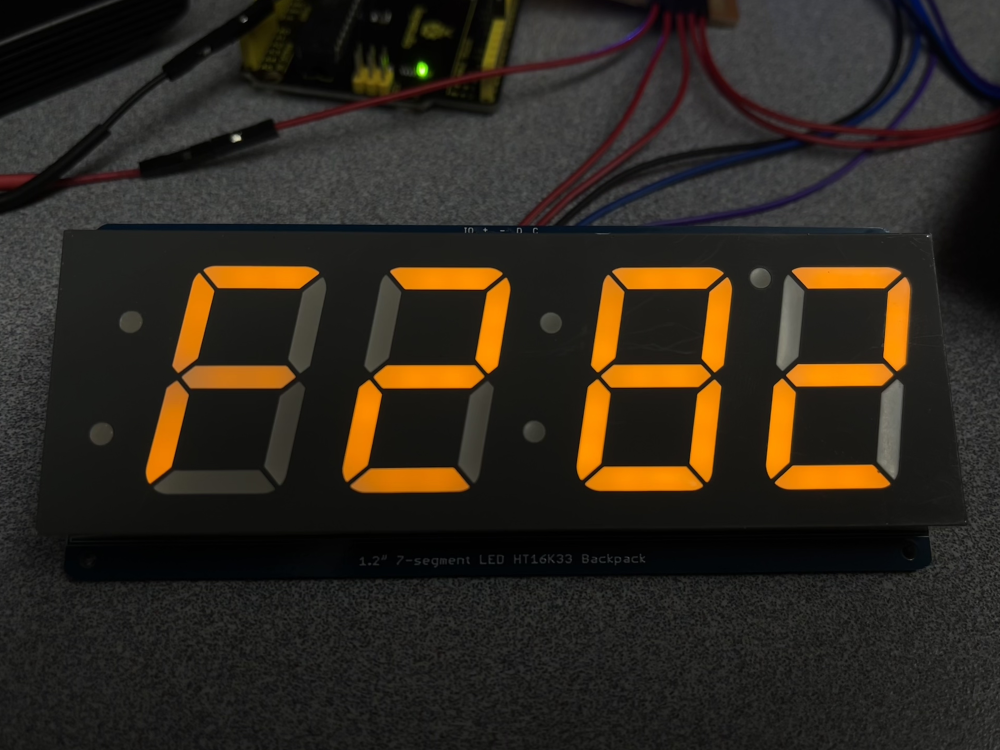
A close up of one of the 7 segments displaying "F282", the name of the specific escape room.

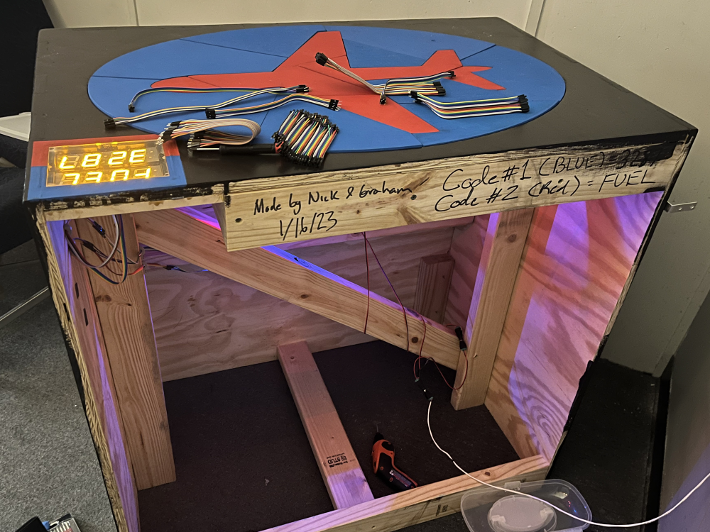
A view of the completed table, though the back of it (normally pushed against the wall) showing the inside electronics and on top the plane puzzle pieces themselves can be seen.

Development Documentation

Start to finish of how I developed the device.

Part 1 - The Owner's Goals

When initially approached by the owner of the escape room, he essentially wanted me to revamp a puzzle already in the Flight 282 (or F282) escape room (he owns a complex with multiple rooms of different themes). He wanted something that looked much more professional, but more importantly, something that had better electronics running it, as he had been having issues with the puzzle not working right with players in the room.

Part 2 - Initial Plan - Using RFID

My initial approach to this project seemed simple at first, but became too complex very quickly. My initial plan, that I even pitched to the owner, was to implant RFID tags in the puzzle pieces, and then place RFID readers inside the table at designated locations. This idea was a good start, as it would insure no issues with contact and no potential damage to the important parts of the puzzle (a big concern for him, as many players damage players unintentionally). The issue, however, arose when planning the electronics. A system such as this would require 4 separate microcontrollers, all of which would have to communicate data to a primary microcontroller (or have one of the four act as that). The reason for this is the sheer amount of pinouts a given RFID board requires. Like I said, this system would work, but would be incredibly complex. I spent a lot of time trying to come up with a new and better solution.

Part 3 - A Better Solution... With Sacrifices

After lots of thought, I came up with the idea to use mechanical contacts that would complete the circuit when a puzzle piece was put in place correctly, allowing me to detect such a connection on a microcontroller. This idea would be much simpler: one microcontroller, and simply 8 pinouts (2 per puzzle piece, 4 pieces). There were concerns, however. Using metal contacts on the table would mean the puzzle would be much more vulnerable to damage by players, and ensuring a good contact between the piece and contacts would also be challenging. Ultimately, however, after discussing the options with the owner, I settled on this solution. To solve the other problems, I used springs on the contacts in the table to ensure a good connection, and did so in a way that the contact on the pieces stuck out and the springed contact was embedded in the wood of the table to avoid damage. With a better solution in place, I began to develop the electronics.

Part 4 - 7 Segment i2C Issues

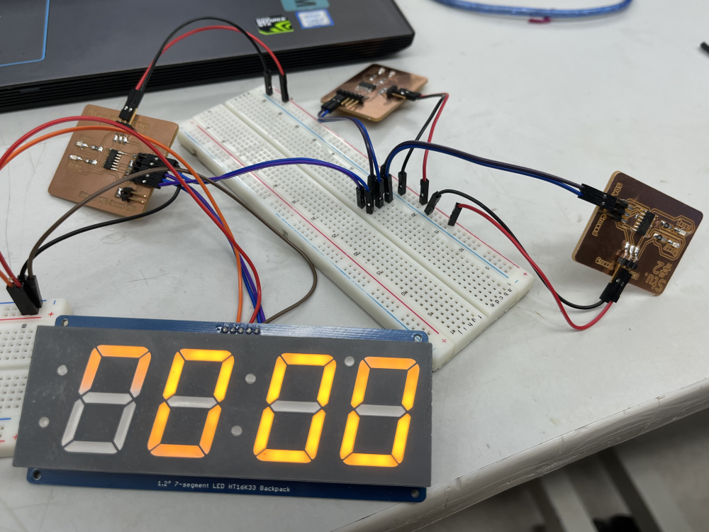
However, as is always with electronics it seems, there had to be another issue. In this case, both 7 segment displays had the same i2C address. Foolishly, as this was before I was aware that these boards could be programmed to use a different address, I designed in KiCAD and milled 3 separate PCBs. A master and 2 student boards, in an attempt to control the 7 segments separately and use Rx Tx between microcontrollers to tell the 7 segments what to show. This, however, was creeping back towards the initial complexity issue of having to use multiple microcontrollers for what should be a simple project. Fortunately, after much digging, I figured out I could simply reprogram the i2C address of one of the displays. This worked, and luckily I was back to just needed a single microcontroller and could proceed with the electronics as I planned to before.

A view of the 3 PCBs that I had designed, milled, and soldered, all with the intention of each controlling its own 7 segment.

Part 5 - The Final PCB & Electronics

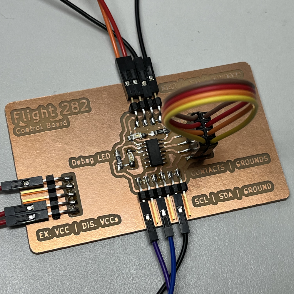
Now with all the conceptual and electrical issues solved, I delved into KiCAD to design the actual final board for the project. I used an ATtiny1614 microcontroller, as well as a host of pinouts. The pinouts included 2 pinouts per piece for the contacts (so 8 total), as well as a line of pinouts for VCCs for the displays and microcontroller, a full line for GND/SDA/SCL, an one for UPDI to program the onboard microcontroller. After testing, and writing the code of course, the board worked perfectly and was ready to be installed as a part of the puzzle. I was only in charge of the electrical portion of the project, so my work for this project was done here.

A view of the finished PCB, soldered and working.