Final Code & Wiring
The final code and wiring for the entire project goes as follows:
	//Libraries
	#include "Arduino.h"
	#include "Wire.h"
	#include "RTClib.h"
	#include <Wire.h>
	#include <Adafruit_GFX.h>
	#include <Adafruit_SSD1306.h>

	//Vars
	#define SCREEN_WIDTH 128
	#define SCREEN_HEIGHT 64

	//Vars - Devices
	Adafruit_SSD1306 display(SCREEN_WIDTH, SCREEN_HEIGHT, &Wire, -1);
	RTC_PCF8523 rtcPCF;

	int goalDay = 17;
	int goalMonth = 10;

	void setup()
	{
		Serial.begin(9600);
		Serial.println("start");

		if (! rtcPCF.begin()) {
			Serial.println("Couldn't find RTC");
			while (1);
		}
		if (! rtcPCF.initialized()) {
			Serial.println("RTC lost power, lets set the time!");
			SetTime(2024, 8, 15, 11, 16, 0);
		}

		if(!display.begin(SSD1306_SWITCHCAPVCC, 0x3C)) {
			Serial.println(F("SSD1306 allocation failed"));
			for(;;);
		}

		Display("??:??");
		delay(4000);
	}

	void loop()
	{
		//Print time data to serial monitor
		DateTime now = rtcPCF.now();
		Serial.print(now.month(), DEC);
		Serial.print('/');
		Serial.print(now.day(), DEC);
		Serial.print('/');
		Serial.print(now.year(), DEC);
		Serial.print("  ");
		Serial.print(now.hour(), DEC);
		Serial.print(':');
		Serial.print(now.minute(), DEC);
		Serial.print(':');
		Serial.print(now.second(), DEC);
		Serial.println();

		DisplayCountdown();
	}

	void Display(String text){
		display.clearDisplay();
		display.setTextSize(4);
		display.setTextColor(WHITE);
		display.setCursor(0, 10);
		display.println(text);
		display.display();
	}

	void DisplayCountdown(){
		display.clearDisplay();
		DateTime now = rtcPCF.now();
		int daysLeft = (goalMonth - now.month()) * 30;

		display.setTextSize(4);
		display.setTextColor(WHITE);
		display.setCursor(40, 10);
		display.print(daysLeft);
		display.setCursor(2, 45);
		display.setTextSize(2);
		display.println(" Days Left");
		display.display();
	}

	void DisplayTime(int fir, int sec){
		display.clearDisplay();
		display.setTextSize(4);
		display.setTextColor(WHITE);
		display.setCursor(0, 10);
		if (fir > 9){
			display.print(fir);
		}
		else{
			display.print("0");
			display.print(fir);
		}
		display.print(':');
		if (sec > 9){
		display.println(sec);
		}
		else{
			display.print("0");
		display.println(sec);
		}
		display.display();
	}

	void SetTime(int y, int m, int d, int hou, int minu, int sec){
		rtcPCF.adjust(DateTime(y, m, d, hou, minu, sec));
	}
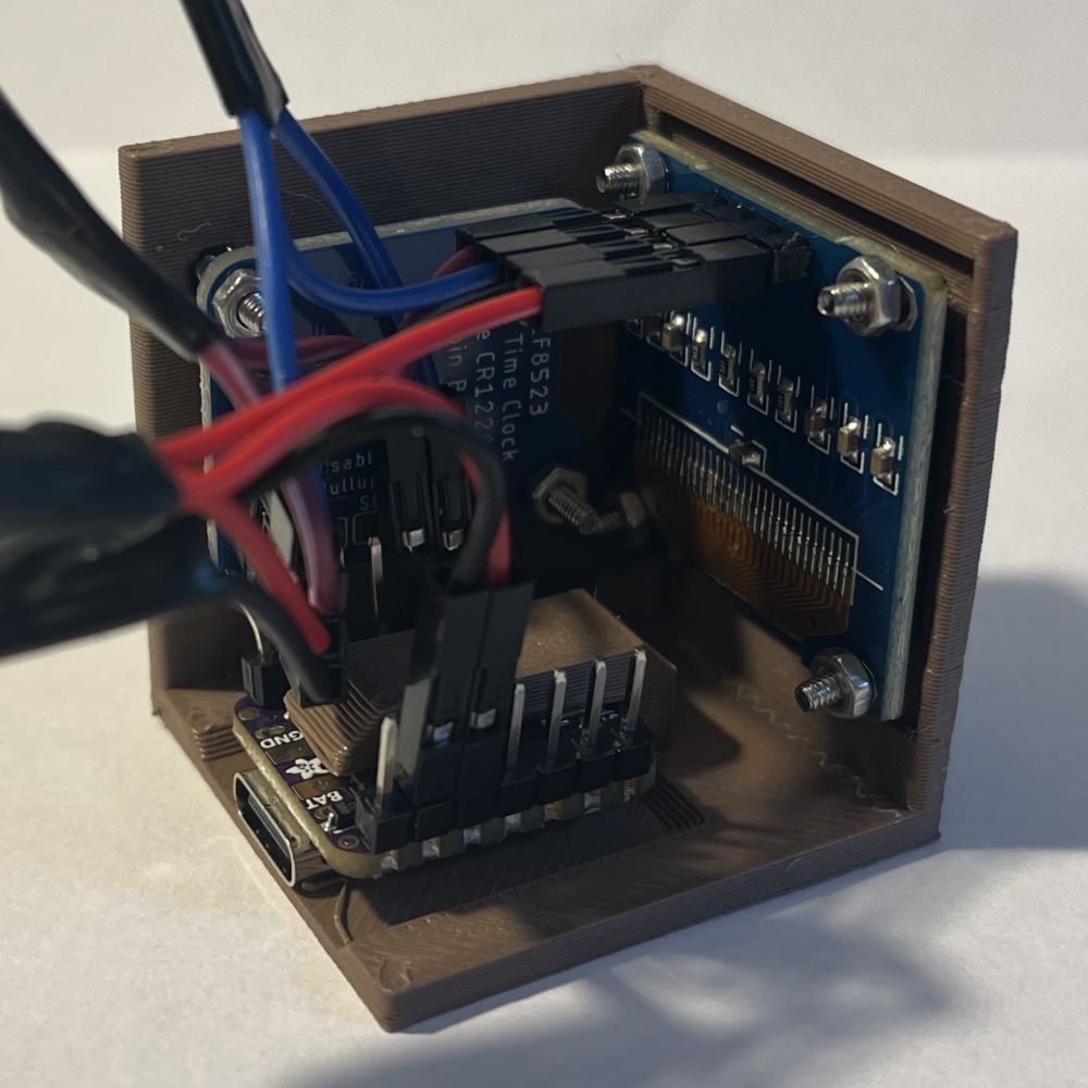
The circuit was wired as follows:
| Other Pin |
ESP32 Pin |
| Screen VCC |
3.3V |
| Screen GND |
GND |
| Screen SCA |
SCA |
| Screen SCL |
SCL |
| Clock Module VCC |
3.3V |
| Clock Module GND |
GND |
| Clock Module SCA |
SCA |
| Clock Module SCL |
SCL |
